The most challenging and exciting project I have ever worked on!
Senior Capstone - Vibram Transparent Inclinable Walkway.
Disclaimer!
This project was completed as part of my senior design program in collaboration with Vibram. The company granted our team permission to share, discuss, and present all aspects of the work in portfolios and professional materials. Any information included here is used with their approval and does not disclose confidential or restricted material. Hope you enjoy!
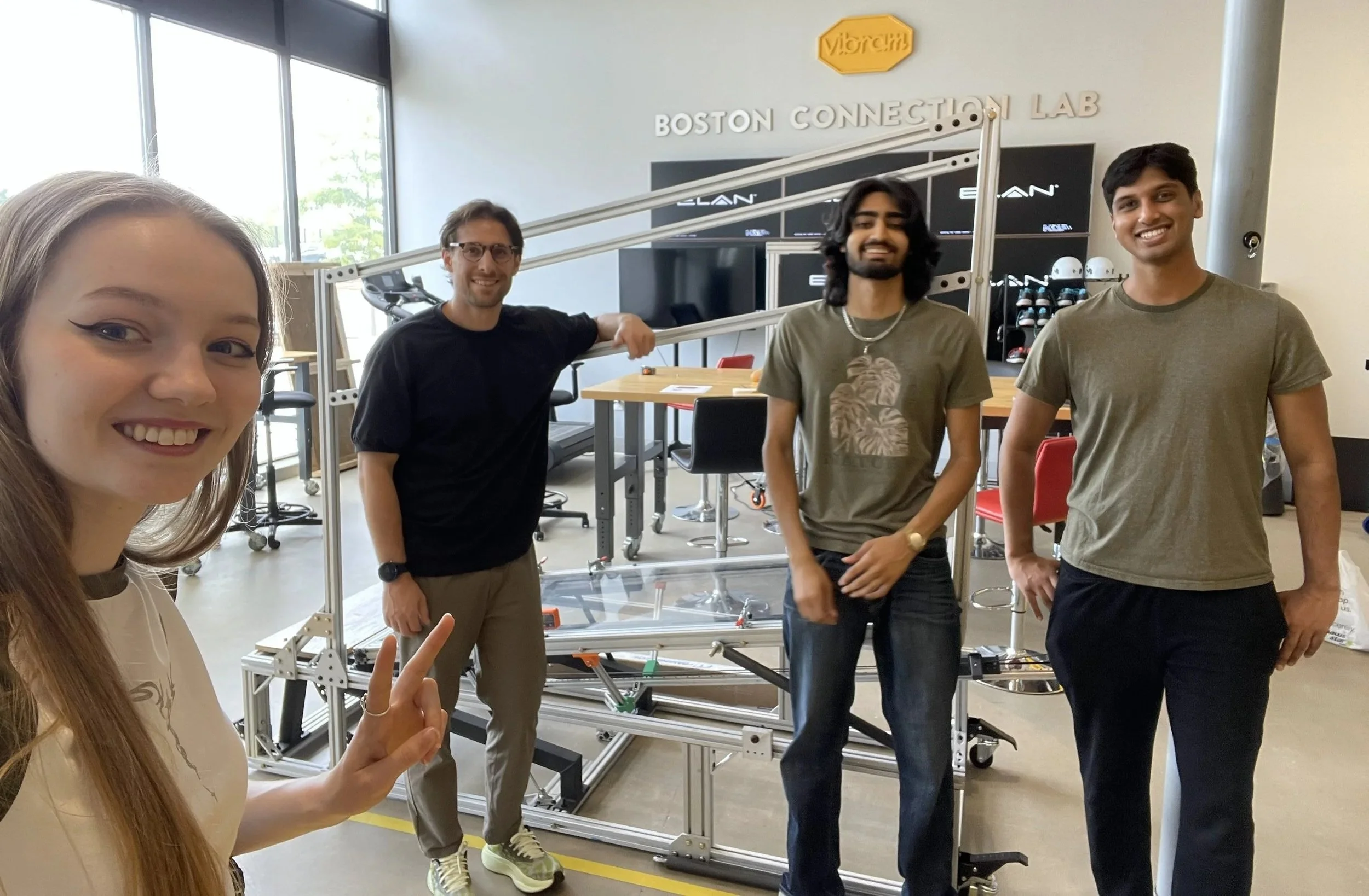
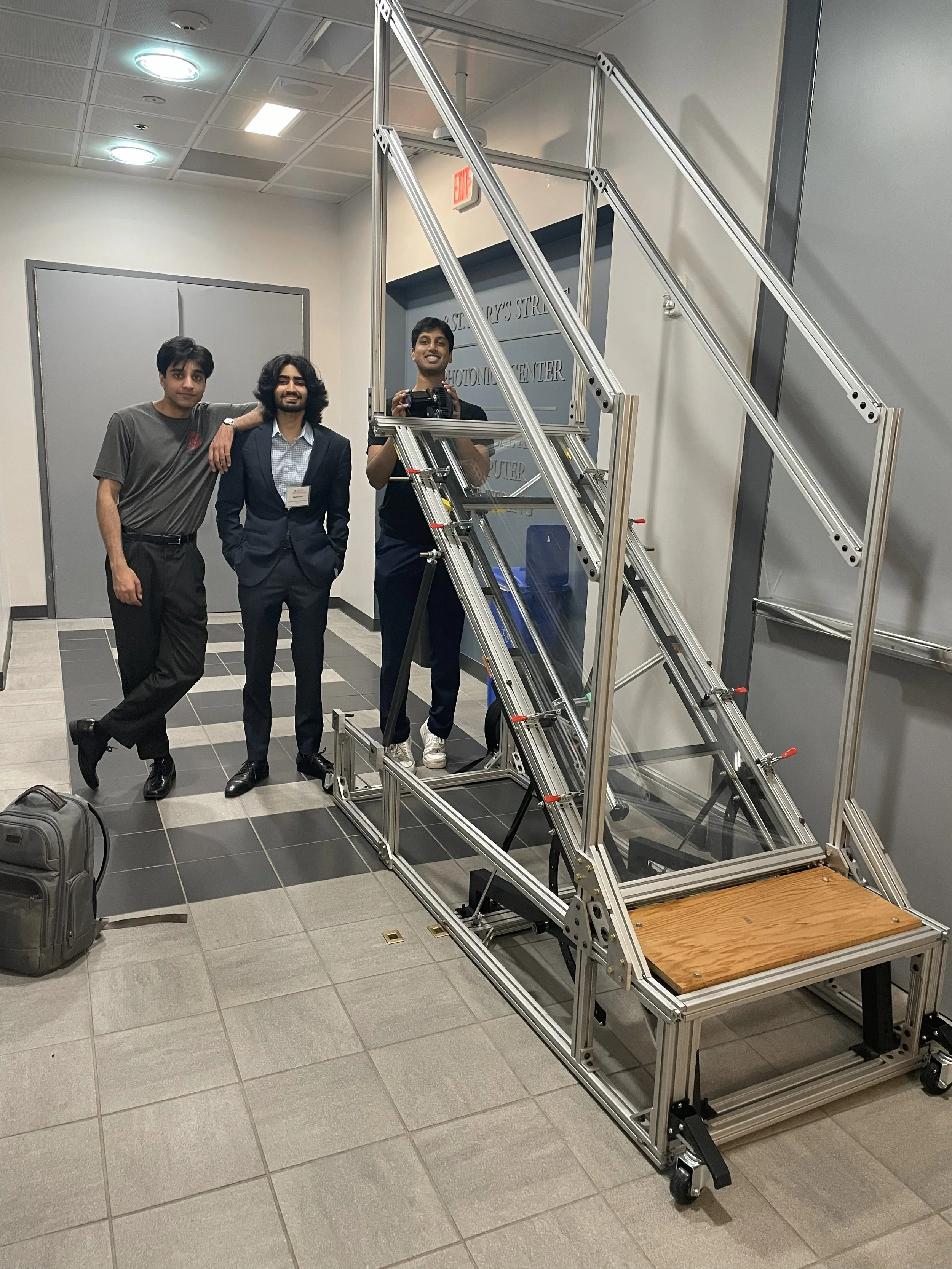
Me and 2 of my teammates (Joydeep and Akash) next to the final build!
Introduction
For my senior capstone in Mechanical Engineering at BU, I worked on a sponsored project with Vibram in a team of 5 to design and build an inclinable transparent walkway for footwear testing. The goal was to create a device that allows engineers to observe how shoe soles deform and grip surfaces while walking at different angles. Since no commercial solution existed, our team designed a fully custom mechanical system from the ground up, focusing on safety and modularity. The final result was a functional prototype capable of supporting a 225lb person with a movable camera mount.
My Role
I served as the team communications lead, CAD lead, and FEA simulation lead. I was the primary point of contact with Vibram and organized our meetings and discussion topics. I was responsible for the SolidWorks modeling, FEA simulations, and leading force/deflection calculations. Furthermore, I contributed to machining, assembly, and testing.
Skills
FEA (SolidWorks Simulation) • SolidWorks CAD • Design for Manufacturing
Engineering Drawings • Structural Analysis • BOM Creation
3D Printing Integration • Prototyping & Assembly • WaterJet
Key Specifications
Adjustable incline from 0–40° in fixed increments
Supports a 225lb person walking with a safety factor ≥2
Transparent acrylic walking surface
5.5 foot walking distance
Mechanical lifting system (no electronics required)
Underside camera system for shoe sole observation
Modular, transportable aluminum frame construction
Initial Prototyping - 3D Prints and Modeling
For the initial few months, we had been thinking of many ideas for lifting the device, and we were unsure of what to pick. We thought of elevator-like pulleys or winches to lift the device, or manual hydraulic jacks at the base, or a simple arm stand used in gym benches that slots into some metal grooves. We had so many meetings of rough calculations of beam strengths, and doing rough drawings of possible designs and ideas. Finally, I created 3D-printed mini models to illustrate our ideas and provide a clearer picture to our sponsors. This helped a lot; our sponsors told us more in-depth specifications and helped us narrow down our ideas after our meeting, where I presented these models to them!
Idea 1 - Hydraulic Jack at base with adjustable arm
Idea 2 - Pulley System with Linear Rail
Idea 3 - Pulley System with Adjustable Arm
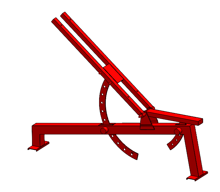
From there, we proceeded to design our first full CAD model, utilizing the supporting strut method with a hydraulic jack. Every meeting would be a feedback loop where my teammates would suggest changes, and I would implement them in CAD. For the design we ended up with, we included handrails on one side of the device, and decided to make our own hinge out of a large 1-inch thick rod, mounted ball bearings, shaft collars, and c-clips. We wanted to make the slotting mechanism with 3 rods of stainless steel and 2 bars of tube steel. This is the model we proposed to Vibram, and we also prepared a BOM for the design, which totalled to approximately 1900$!
Render of proposed model 1 with full BOM prepared
CAD Model with balloons for each unique part for BOM presentation
Design Changes and Negotiations
Our model, which Vibram had received a proposal on in December 2024, was what we were set to go with heading into 2025. However, one member of our group actually recommended we make a different design that revolved around using 2 affordable gym bench frames as the pivot support for the device. They had created a rough mockup in Fusion 360 that got the point across, which is shown below. It was a tough call to make because it meant making major changes to our old model and having to make another proposal to Vibram. It took a week of deliberation amongst the team, but ultimately we came to a decision that it would save us a ton of time on machining and would be more affordable, not to mention it provides a nice area for a step-up plate that would make it easier to walk on the device. Thus, I then modeled our final model to accommodate their idea. I am thankful our teammate suggested this idea and really advocated for it, because in the end, our machining time was probably cut in half because of their efforts!
These design changes were fueled by budget constraints and the decreasing window of time we were facing for ordering and machining. We had an initial budget from BU of $500 for this project, and Vibram promised 500$ as well at the beginning. When we started making our CAD models, we realized we needed at least 2,000$ to make a reasonably safe design. This ensued a 3-month negotiation from December to the end of February, where our team would make proposals and presentations to both our sponsors and BU to convince them to fund the project fully. Finally, we convinced each party to give 1400$ and we were able to complete the project in 1.5 months of machining.
All the advice and critiques for the first design from Vibram.
Our teammate’s mockup of a potential gym bench design!
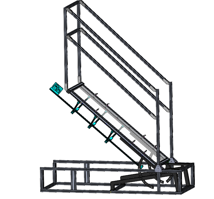
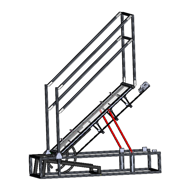
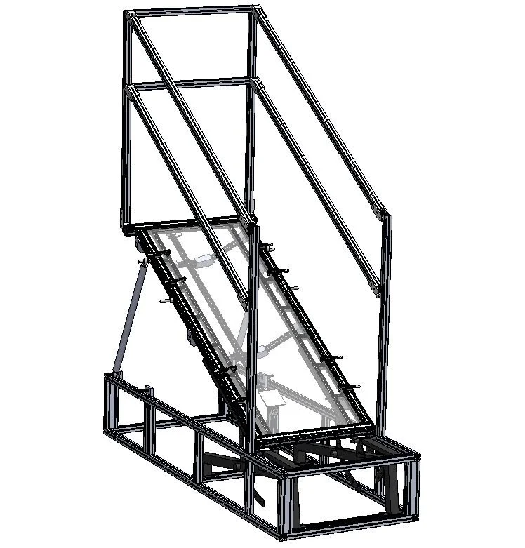
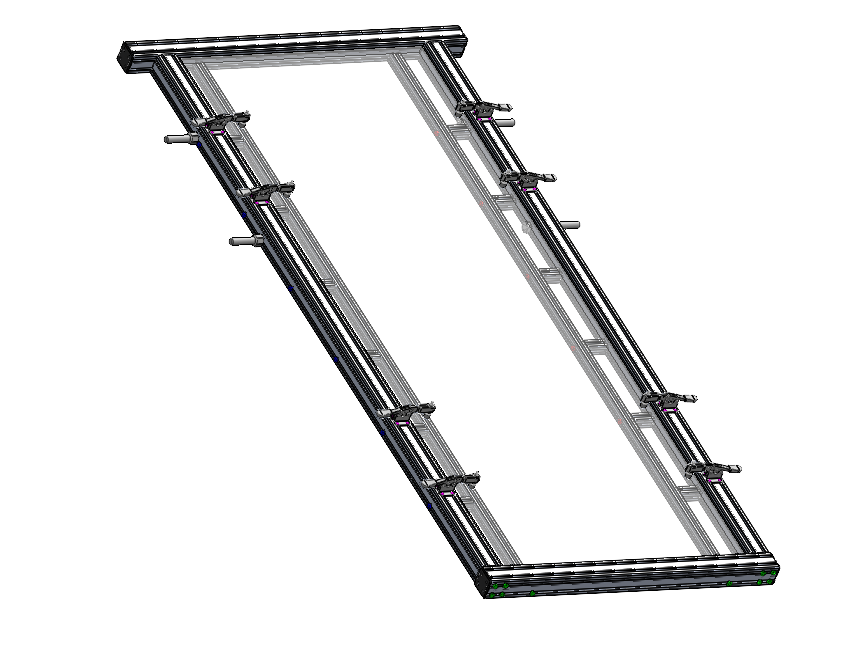
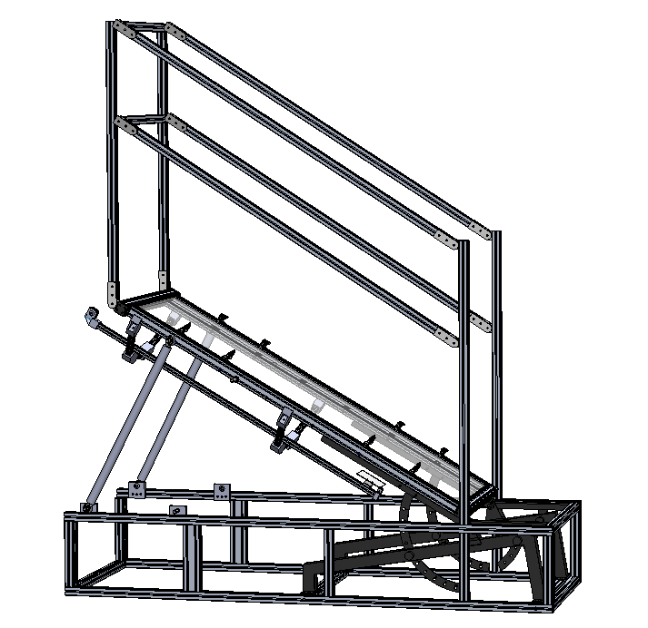
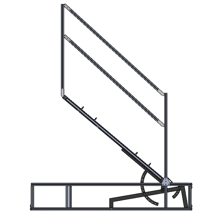
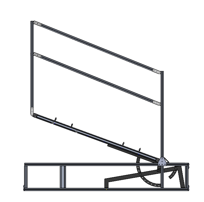
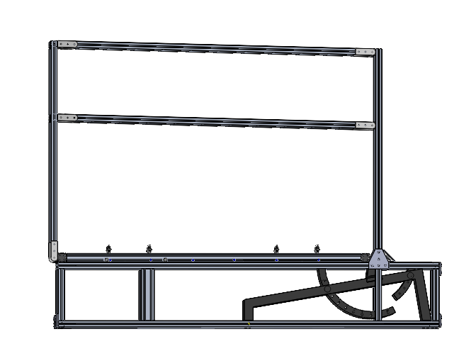
Final CAD Design
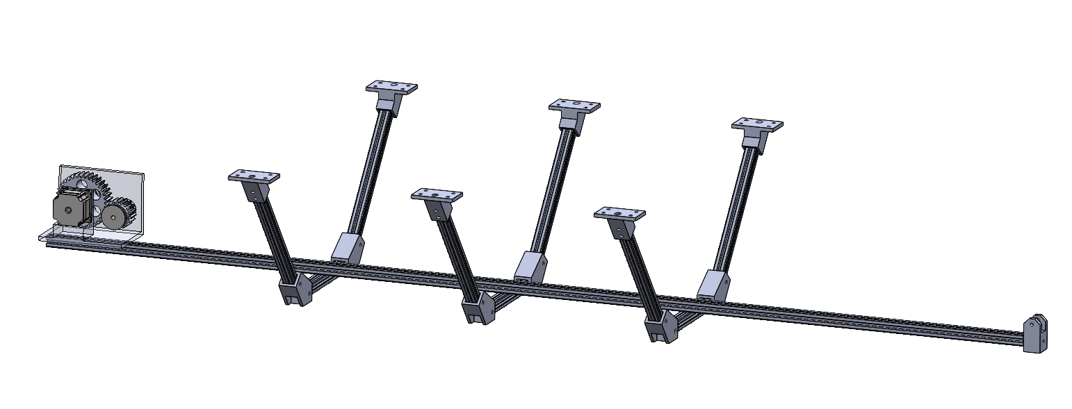
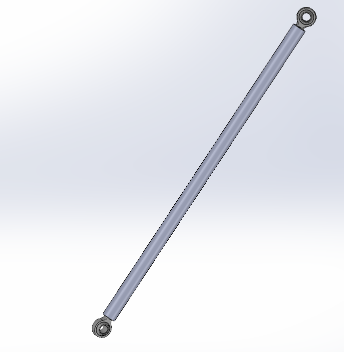
Our team devised a final model that would have the gym bench at the front of the device to serve as a pivot point and utilize safety struts for securing the angle of the frame at increments of 10 degrees. The frame would be lifted up and down by hand with the assistance of 2 gas struts that each exert 100 pounds of force upwards. There is a large linear rail at the bottom of the device that is held to the frame by 3d printed connectors, and the camera mount sits on top of the rail and is belt-driven. The camera can be positioned at any section below the acrylic as per the user’s wish. The acrylic plate is placed in the frame and held in place by a total of 8 toggle clamps. The handlebars are uniquely in a parallelogram format that utilizes 10 hinges. The reason for this design decision is so that the user can have more space while walking at the end of the walkway, since a fixed handlebar that is always perpendicular to the frame will point towards the user’s head at higher inclines and limit the available space. I made a 360 animation and a photoview render of the design, which can be seen below.
This was the largest assembly I have ever made in solidworks and it taught me how to optimize performance and keep things organized for modeling. I also had to learn how to present it nicely to clients and back up the design decisions in meetings.


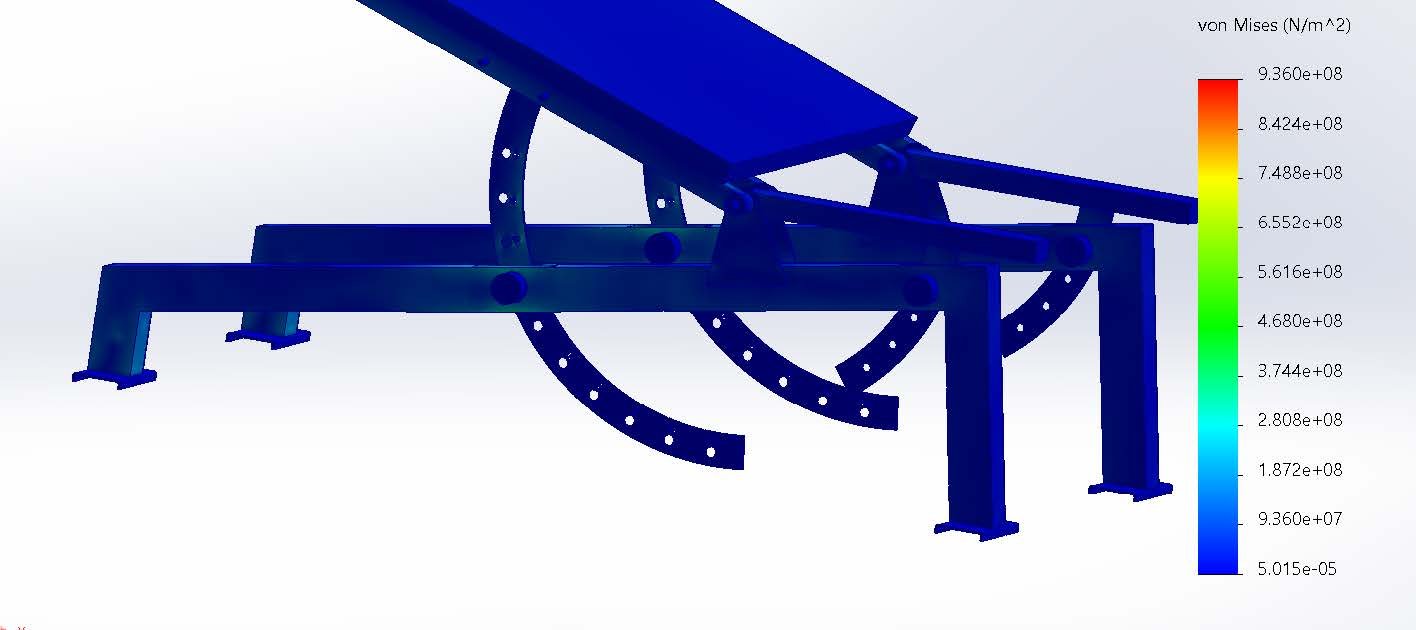
Material Selection and FEA
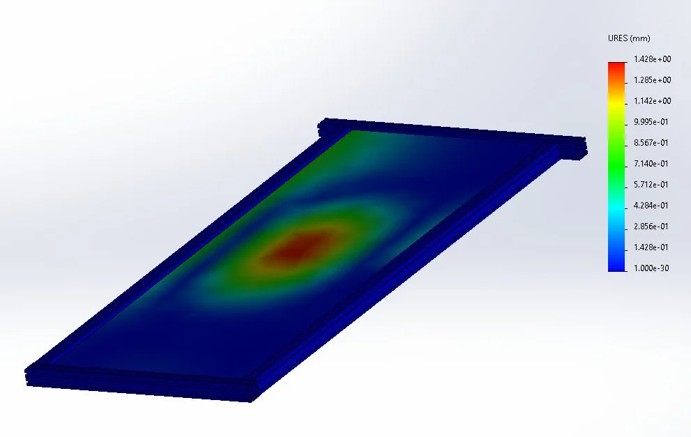
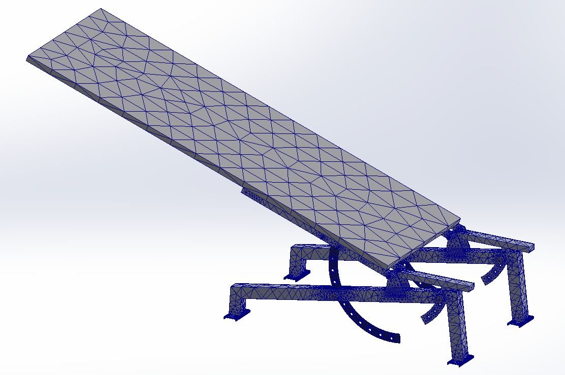
I led the structural simulation work to ensure the walkway would safely support a user at maximum incline. I used SolidWorks Simulation to run multiple FEA studies on the acrylic plate, aluminum frame, and gym bench under a 1000-lb load case. The forces were usually input onto a small rectangular section that is approximately the size of a human foot on different parts that would mimic the force concentration of a walking motion. These simulations helped us determine the optimal acrylic thickness and the strength of the 8020 bars and gym benches. I had to learn how to refine mesh strategies and boundary conditions so our results better reflected real-world scenarios without taking too much time. Even though they were static simulations, we ensured that we used an adequate factor of safety to compensate.
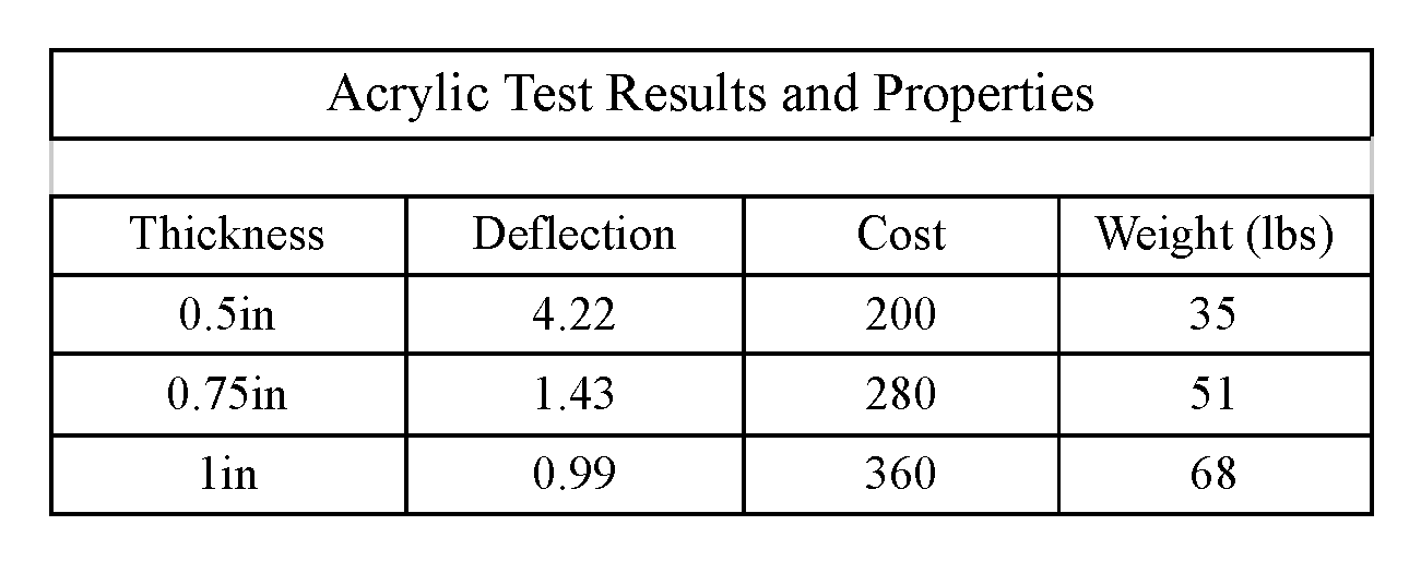
To go in depth about the acrylic results, we found that the acrylic thickness needed for safe use (factor of safety of 2 for a load of 1000lbs) is 0.42 inches. However, we could only choose acrylic in increments of 0.25 inches, so the available choices for us were 0.5in, 0.75 in, and 1in thick acrylic. I then tested deflection for each acrylic thickness and compared each plate’s results to the cost and weight. Weight is important because a lighter plate would be easier to lift up and down for angle changes. After comparing the different parameters, we ended up going with a 0.75-inch thick acrylic plate.
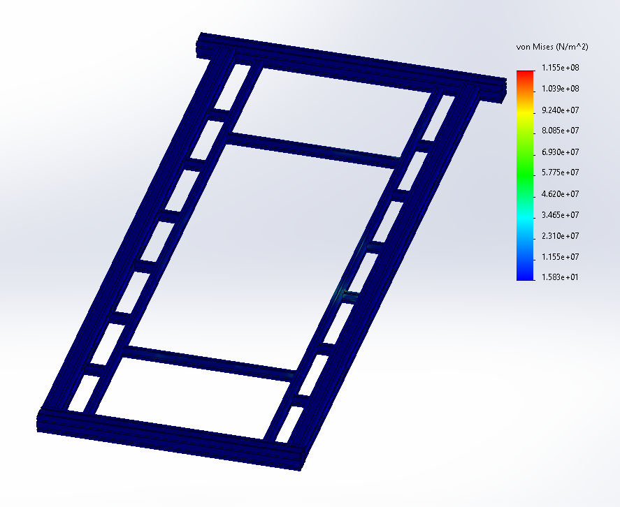
I then tested for the integrity of the 8020 beams in the frame. The frame was composed of 2020 and 1010 aluminum beams made of AL 6061-T6. These t-slots were tested under distributed loads in the area of 200 kPa, or 40 psi.
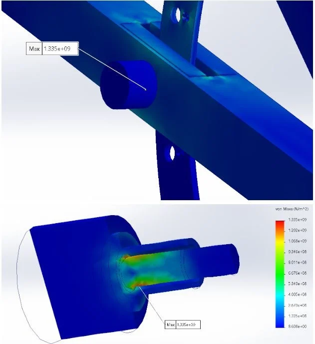
We tested the gym benches and pins just to check what loads the pins could take, just as a preliminary way to check the failure modes. We realized the pins, if used alone as the sole method for securing the acrylic and frame, would endure loads 5x their ultimate stress. So then we started developing the safety struts.
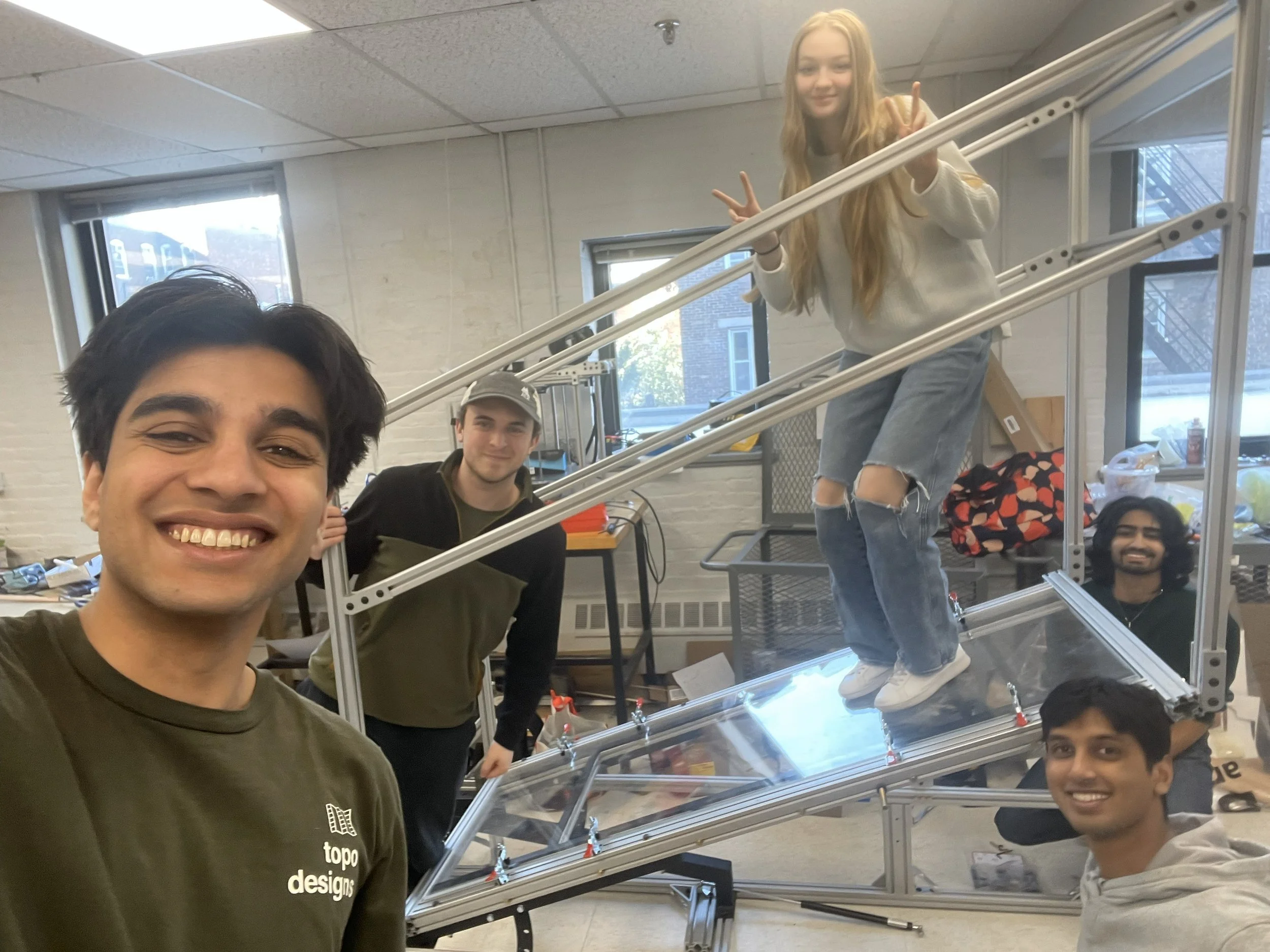
The Fun Part! MACHINING and BUILDING!!!
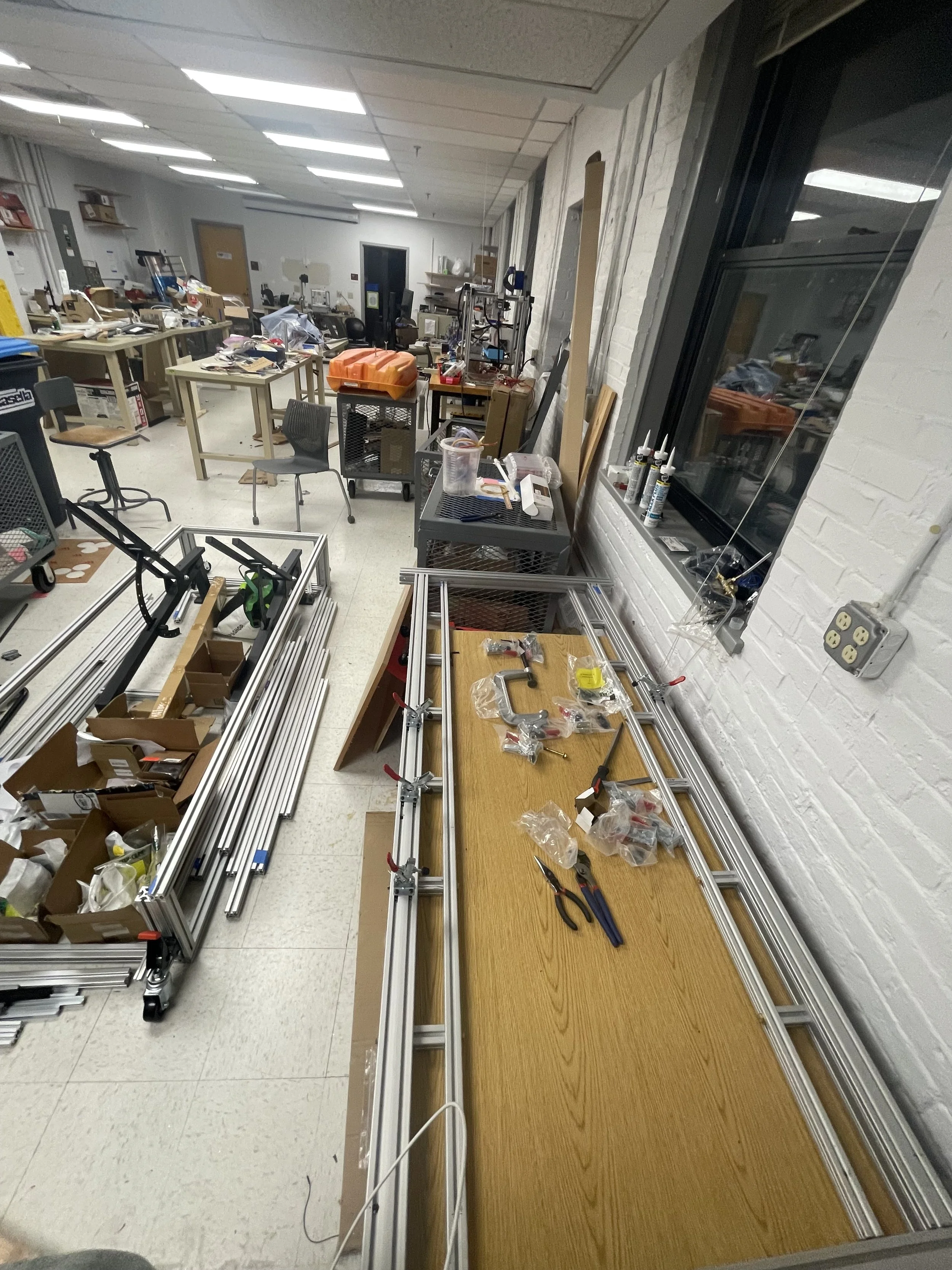
I was heavily involved in the hands-on fabrication phase, serving as the right-hand to our machining lead, Charlotte. I had to measure each bar in CAD and provide drawings to everyone, showing how long to cut the bars and where the holes should be located. I worked with my team on cutting, threading, and assembling every single bar of the build. We used tools like NC mills for finding precise locations for holes, large saws for cutting extrusions, tapping kits for threads, and a few other processes as well.
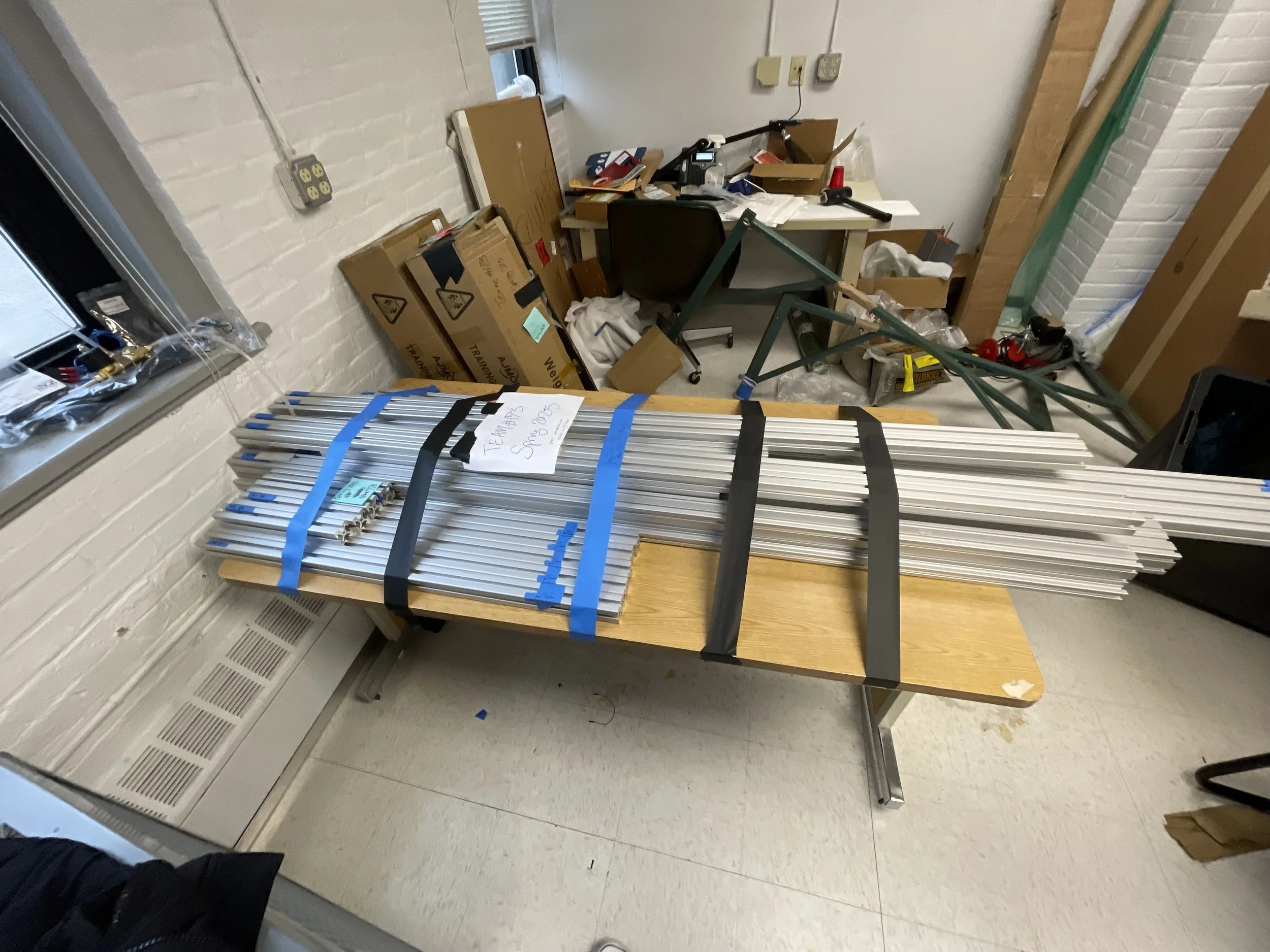
All of our raw 8020 bars arrived!
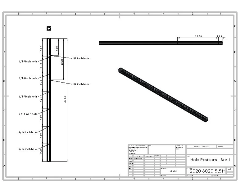
Drawing I made of 1 bar that needed holes

Akash and Alex tapping threads into the long bars
We finished the frame that holds up the acrylic
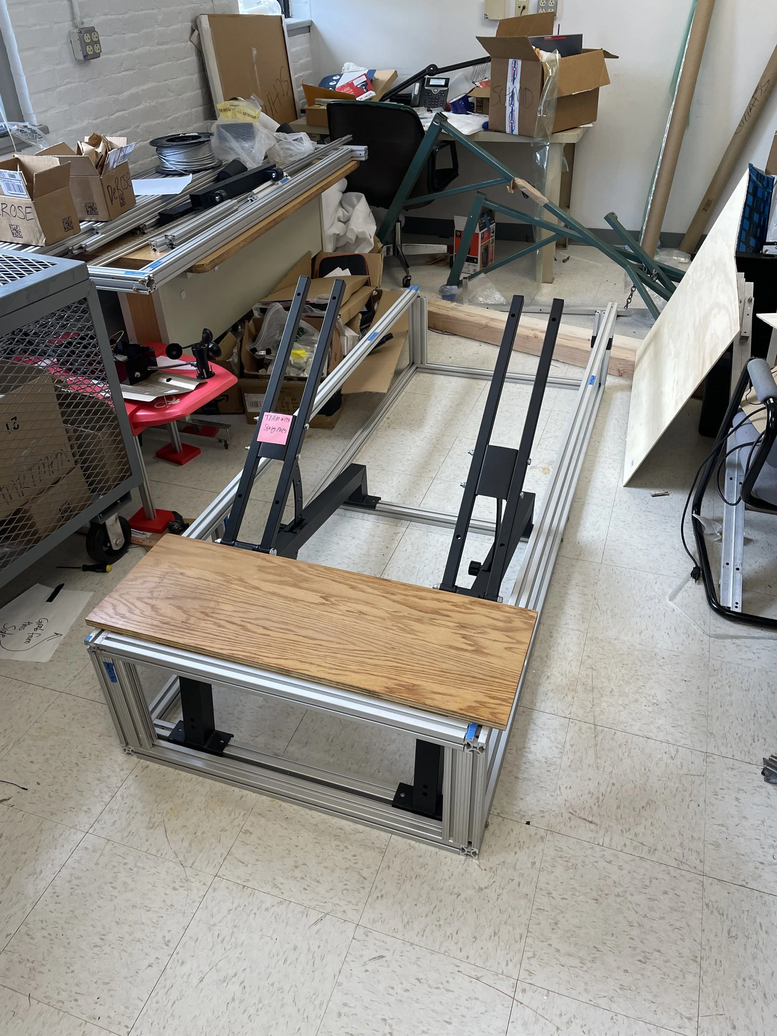
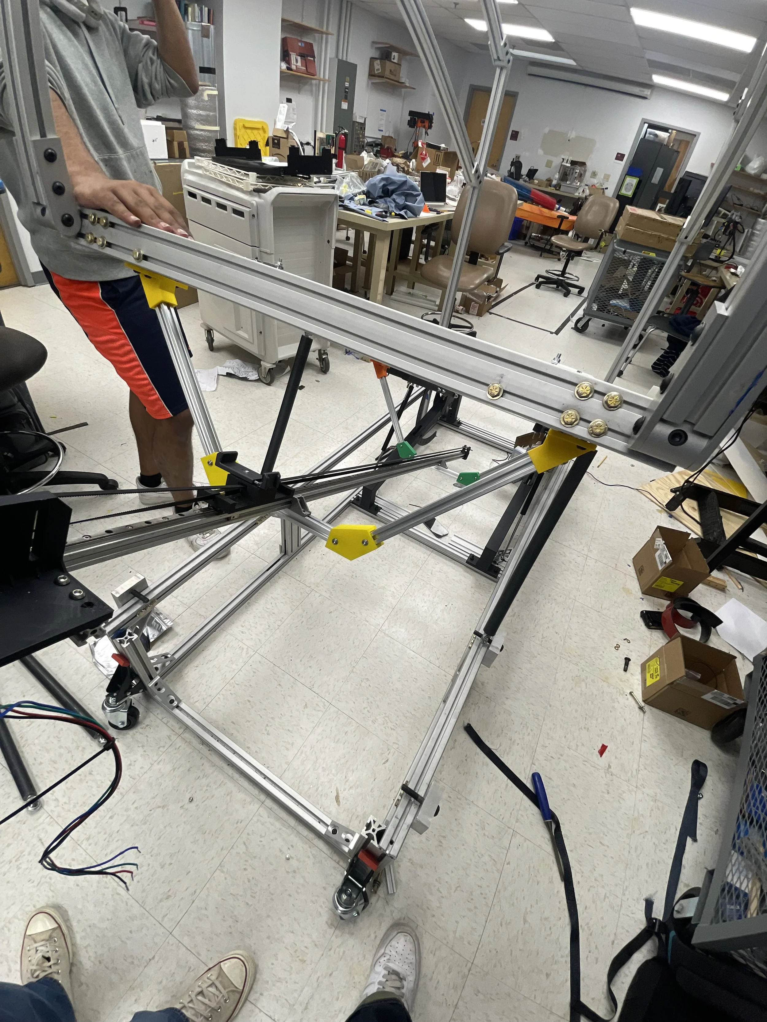
Assembling the base structure with gym benches and a step up platform

Me hanging out after a lot of progress with the base frame
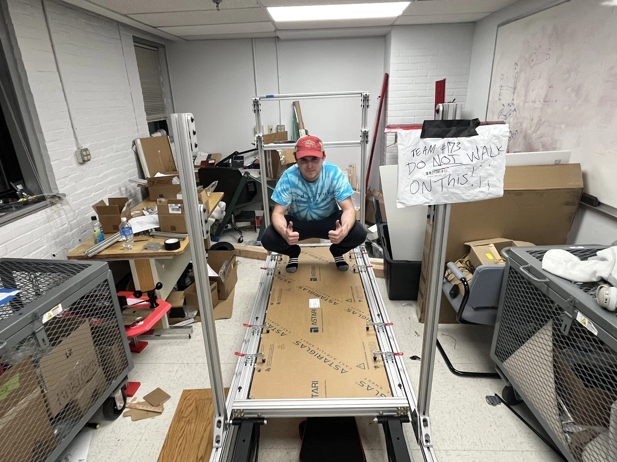
Alex sitting on the walkway now that the acrylic is on top! The protective sheet is still on the sheet for no scratching
Installing the camera rail with 3D prints and linear rails
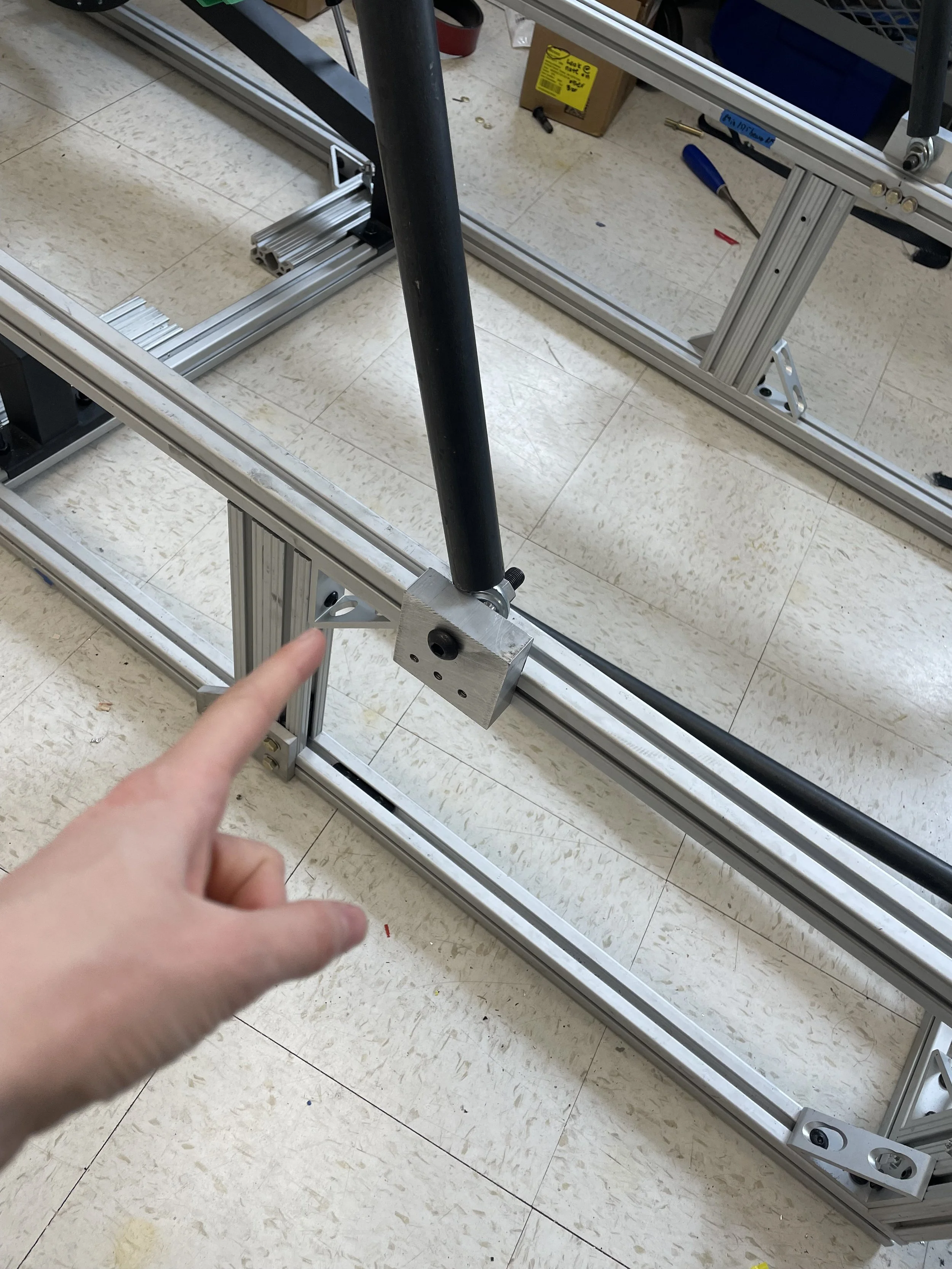
Attaching strut supports to base frame
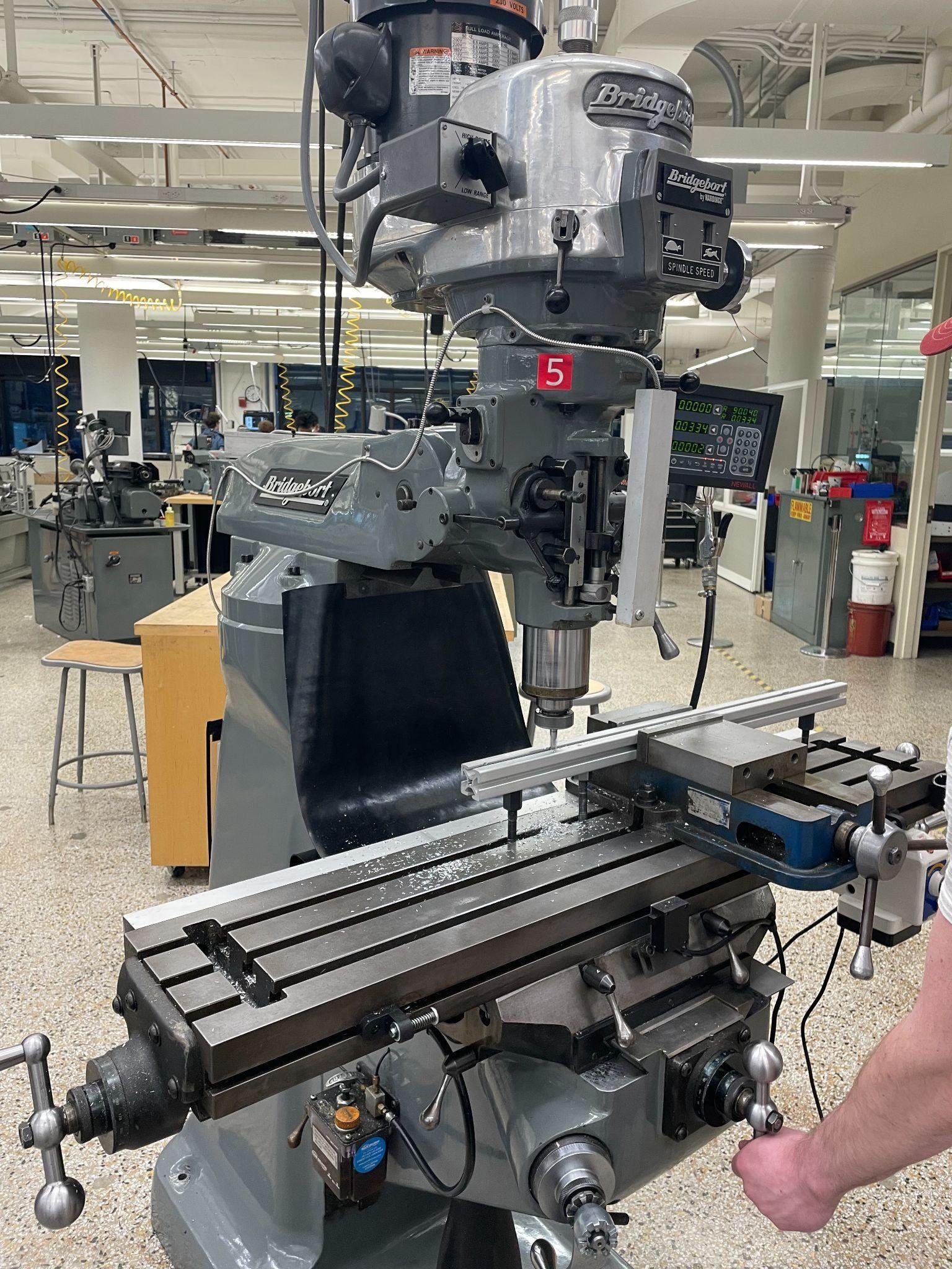
Setup for drilling precise holes in 8020 bars using NC mill

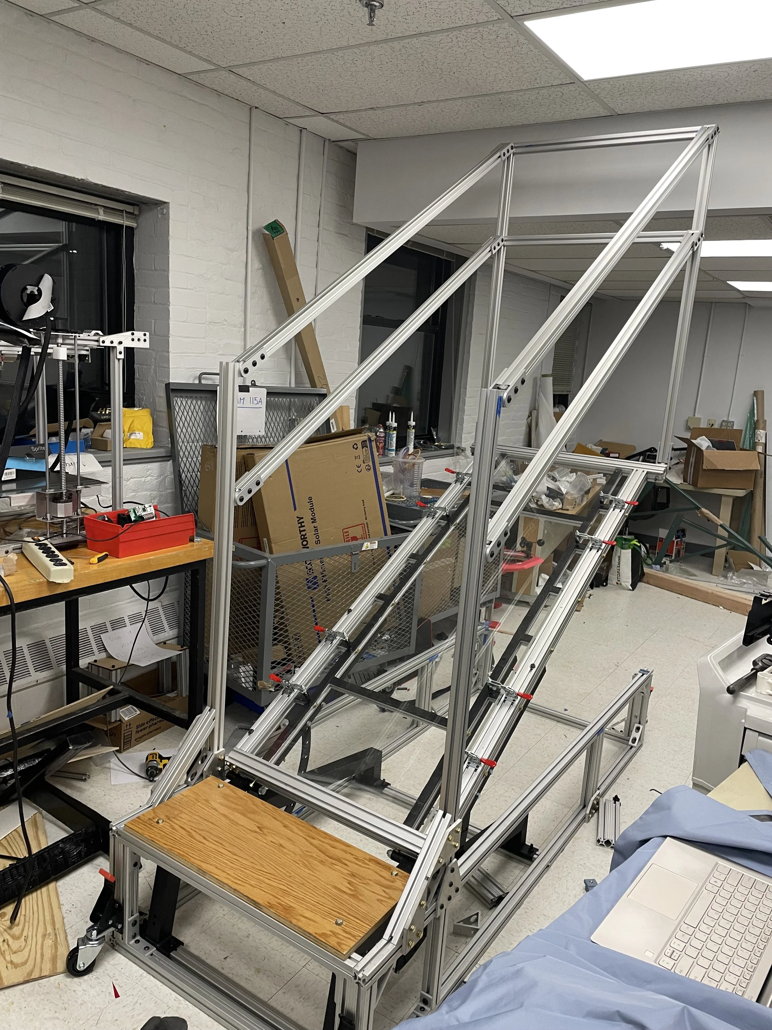
Almost done! It looks beautiful
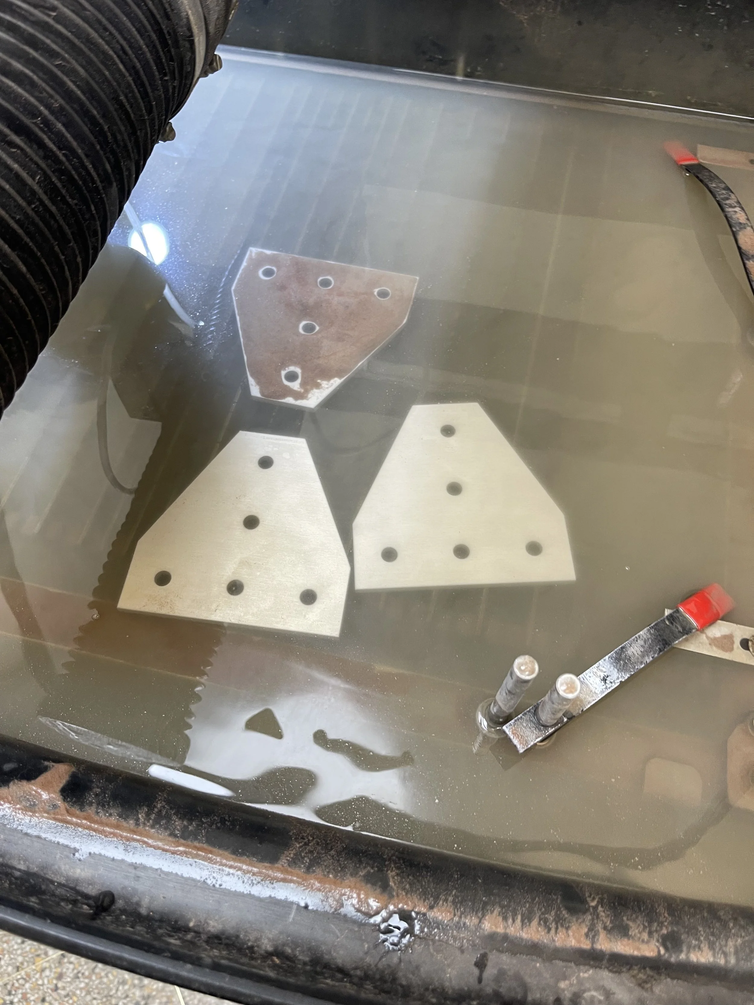
WaterJet Cutting Sidequest
I also did more specific work like printing all the 3D prints, and waterjet cutting the aluminum gussets. I did this side project because we got spare aluminum plates from the storage room, and it was the exact same material and thickness as the gussets that we needed from the 8020 website. That meant I could easily make dxf files, cut the parts, and save our group over 100$ (each one on the website is 12$) from making it myself!
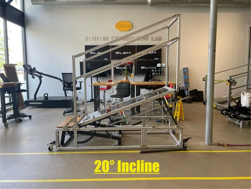
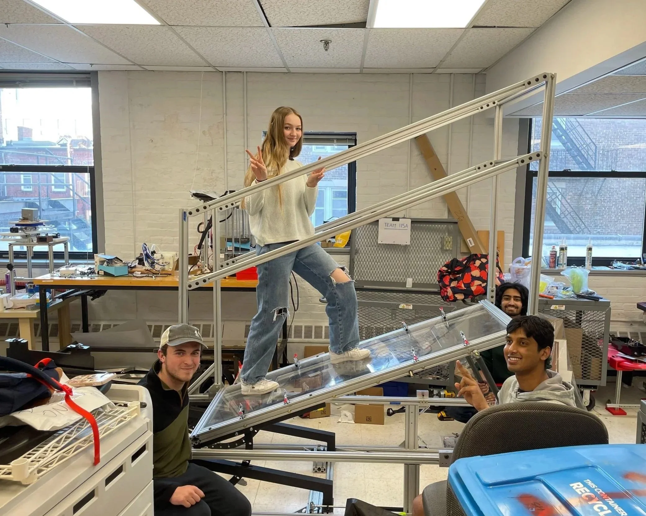
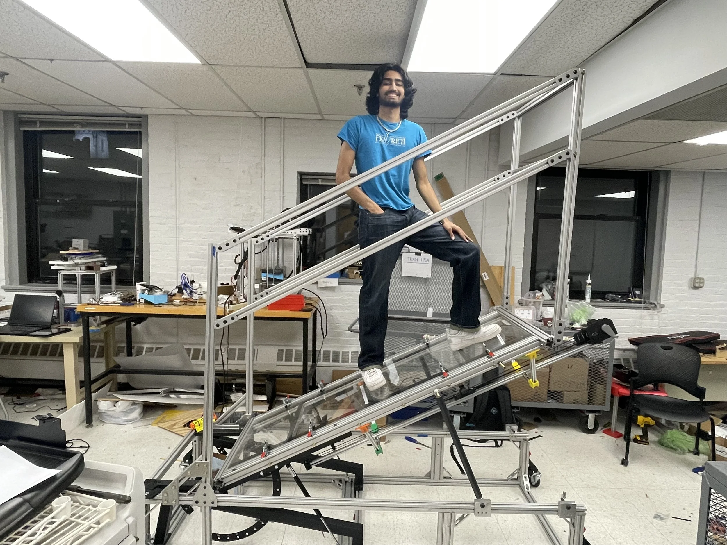
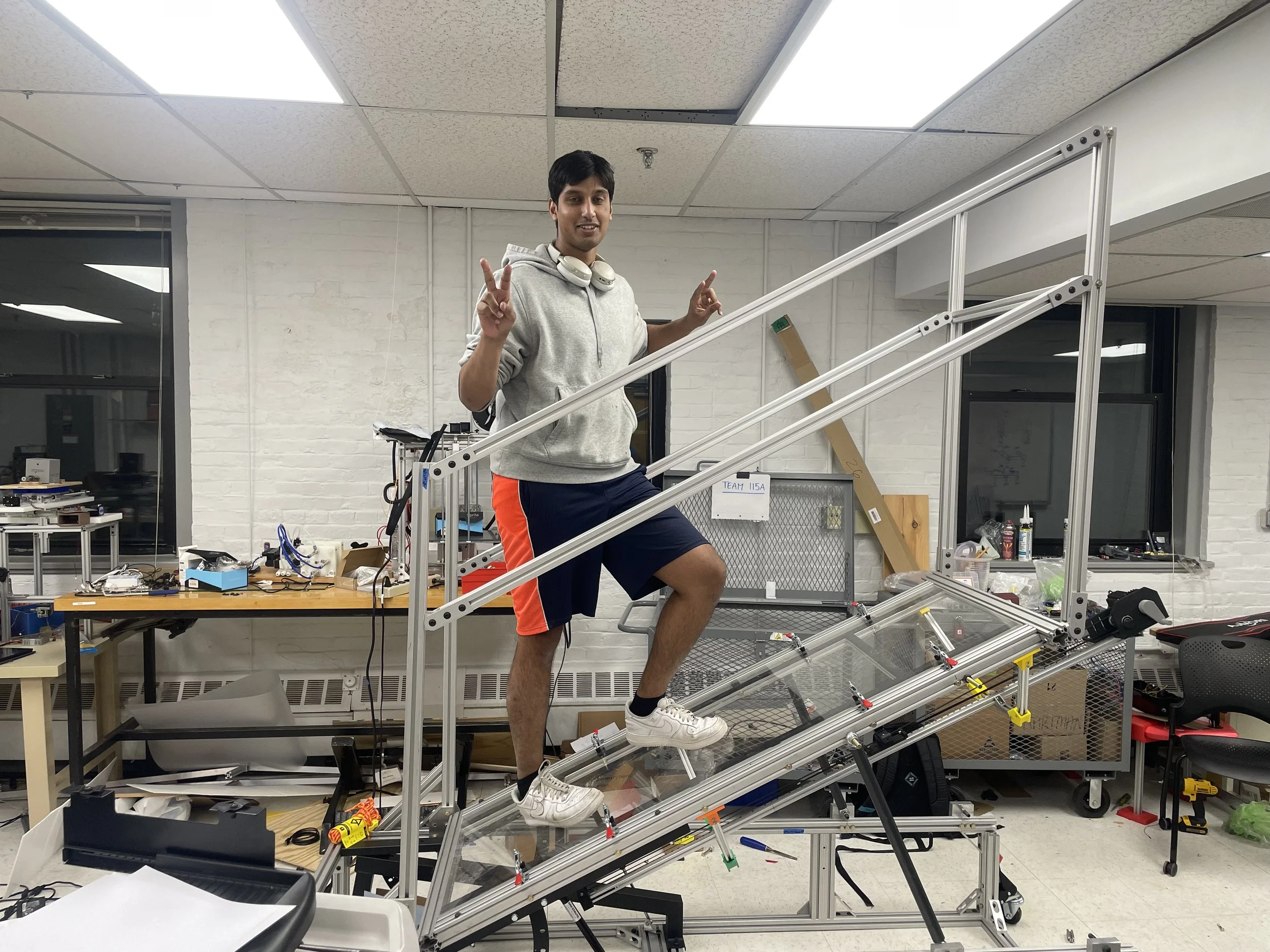
Final Build Complete! Results
We successfully fabricated the design and delivered it to Vibram’s Boston Lab. Below are pictures of the product at different angular configurations. For the delivery, we rented a U-Haul truck and took a half day to drive it to the office and reassemble some components! Our sponsors were happy with the device, and it will be used heavily for testing their new prototypes and products.
This project truly made me realize the complexity of real-world engineering projects. Previously, my university projects had a lot of guidance and could usually be completed with 3D printing or simple, guided machining from professors or teachers. The Vibram project pushed me to learn with my teammates about the soft skills and hard engineering skills needed to be successful. We learned how to best communicate information to each other and also our sponsors, that tries to make things as simple and organized as possible. We had to learn how to budget and negotiate with money to secure funding. We had to navigate making complex CAD assemblies and sourcing parts ourselves online. We had to spend long days and nights planning and machining all the parts, and also adapting to unforeseen errors on the fly. Most importantly, we realized that this device is dangerous to the user, and for the first time in our engineering journey, someone’s health and safety is dependent on us making a safe product. We completed rigorous calculations and FEA testing that held a special weight in our heads, because we knew our calculations would have real-life consequences. I am very proud of this project, and I believe it has truly shaped me in the best way possible as an engineer.


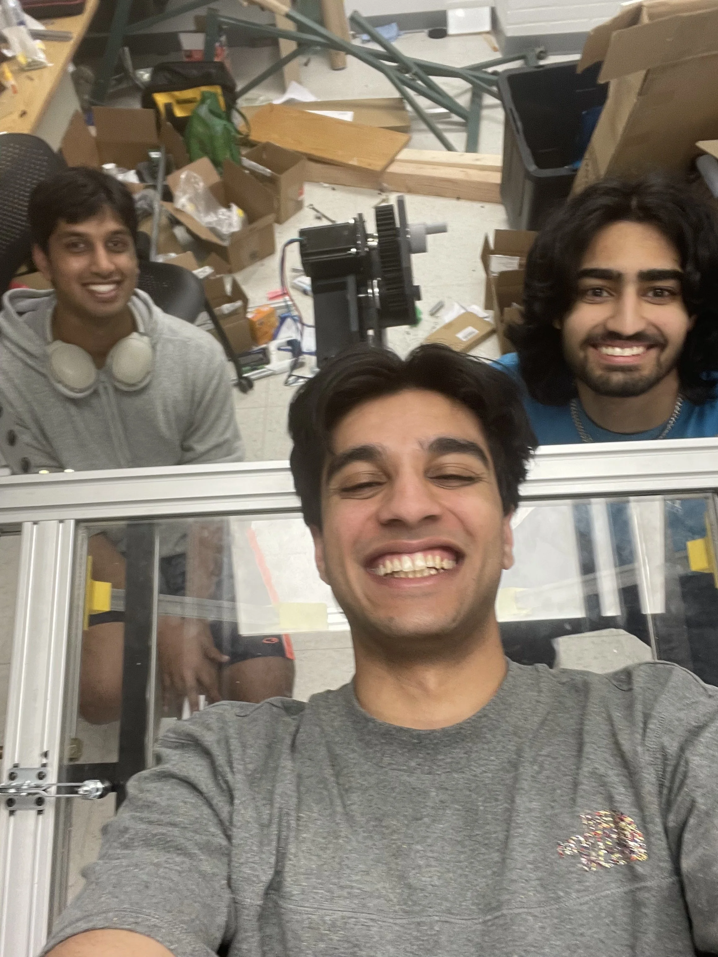
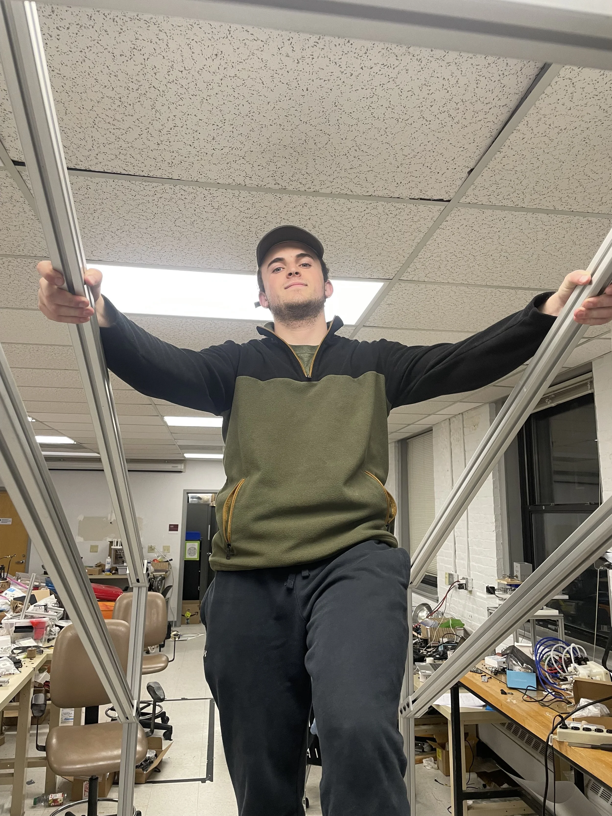
Fun pics with the gang!


Final Words
Thank you to Mr. Maier and Ms. Whited at Vibram for being great sponsors. They were supportive and provided important guidance that made us grow as engineers. I also want to thank Professor Dibella for all his support and help as our faculty advisor. Lastly, thank you to Professor Linn for the financial support of the department and his guidance that made this project successful.
I am very grateful to my teammates: Charlotte, Akash, Alex, and Joydeep. We worked together for 8 months non-stop and endured so many challenges and hard moments together. We had to relentlessly negotiate budgets with our clients and the school, had long weekly meetings for CAD designs and calculations, went through tough days and nights of budgeting and purchasing materials, planned all machining operations, and went to EPIC and machined all the parts in less than 1 month. I learned a great deal from this project, both in terms of its technical aspects and its collaborative elements. My teammates have made me laugh and enjoy the journey of this whole project, and I cannot express how thankful I am to them for lightening my mood and teaching me how to work in a team environment.