2.5 Degree of Freedom System- Drink Dispenser
A fun project for the Electromechanical Design class in 2023!
Introduction
For our Electromechanical design class, my group of 4 was tasked with designing a 2.5-degree-of-freedom device utilizing NEMA 17 stepper motors. We decided to create a drink dispenser! Through weeks of CAD work, we were able to create a product with 2 degrees of freedom in the x and y directions for moving cups, as well as 0.5 degrees of freedom through a peristaltic pump.
My Role
I was the lead for CAD designing and 3D printing for the device. I also worked alongside my teammates to complete the G-Code programming for the stepper motors and the machining of the bars.
Skills
SolidWorks CAD • Design for Manufacturing
3D printing • Prototyping & Assembly • Electromechanical Design
First Step - Belt Drive
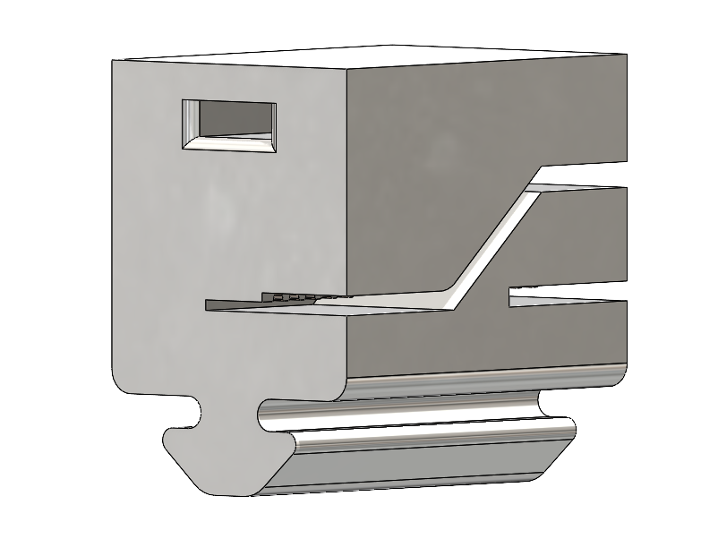
We first made a device to move a slider in 1 degree of freedom. We utilized a Nema 17 stepper motor, an idler pulley with an axle, and a GT2 timing belt. We 3d printed the end caps to hold the motor and idler pulley, and designed the slider to fit into a 1x1-inch 8020 aluminum bar while also friction-fitting the GT timing belt with the ridge openings. We connected the motor through screws in the motor holder, and utilized a press-fit to hold the axle and idler pulley on the other end. The images below show the final designs. The motor holder shown is from the second stage of testing because the CAD for the previous version was altered.
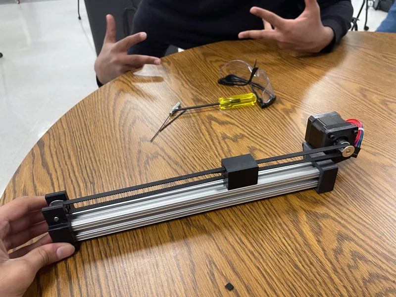
completed belt drive section!
idler pulley holder
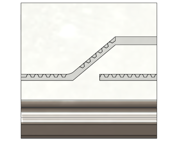
linear slide side view

linear slide isometric view
Peristaltic Pump version 1 (failed)

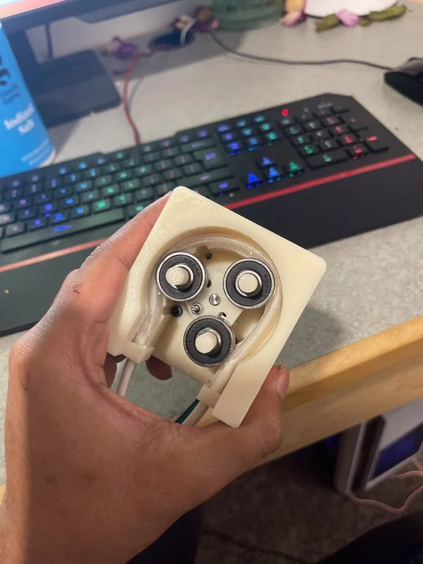
Peristaltic Pump version 2
Peristaltic Pump Designing
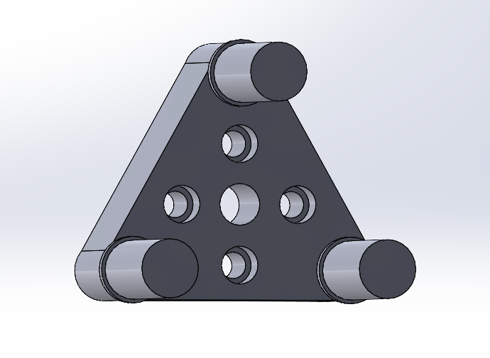
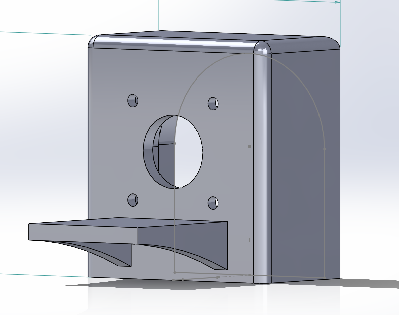
The pump I designed featured a strong outer housing and a triangular mount that is attached to the motor. We put 3 ball bearings on a triangular piece and situated a silicon tube on the outskirts of the opening. The motor is situated on the back of the holder. The ball bearings squeeze the tube and push the liquid/air to create pressure as they rotate. The first prototype failed because the bearings were too close to the wall and thus created too much friction to rotate smoothly. We made the frame opening bigger for the second prototype and adjusted the spacing of the ball bearing rods accordingly.

Full Cad Assembly!
Full CAD Designing
For the machine, we decided that there would be an x-axis slider on the bottom that would hold the drinks, and a y-axis slider on the top of some bars to hold the nozzle for liquids. Our prototype design was decided to be the x-direction slider that we would secure on the ground, and the y-direction slider would be on the top. Thus, if I reference the y-direction, it is the top nozzle slider.
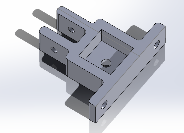
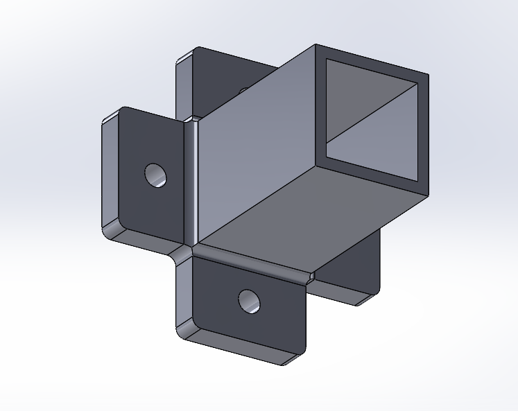
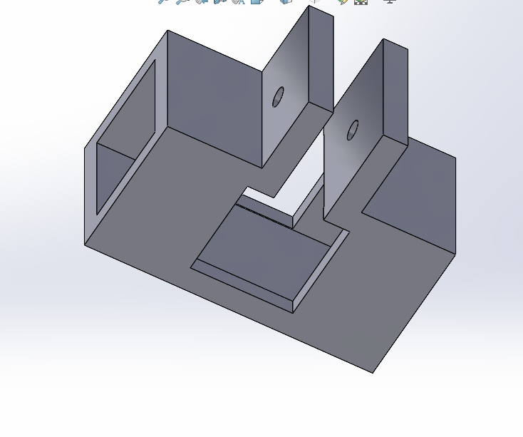
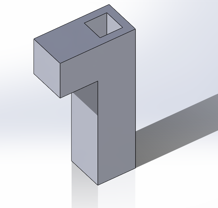
First, we made 4 pillars for the bars that we could screw in some quarter-inch screws from the bottom to secure them. The bars would be screwed into the pillars, and then the pillars would be screwed into the wood. Next, 4 corner connectors were made so the bars could be connected horizontally to another bar at the top. Then the y-direction connectors were made such that they would perpendicularly connect bars while also making a holder for the motor and pulley. The perpendicular bar would be holding the slider with the nozzle. The slider with the big square on top was made as the x-direction slider that holds cookies, which we repurposed to hold cups. The regular slider from the prototype was used in the y-direction. The nozzle (L-shaped piece) will be attached to the slider on top to act as a holder for a silicon tube.
A 3D model of a metal bracket with multiple holes and rectangular cutouts, designed for structural support or assembly.
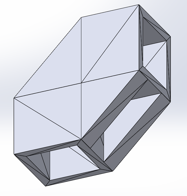
A 3D geometric wireframe model of a rectangular prism with additional internal structures and shading to show depth and edges.
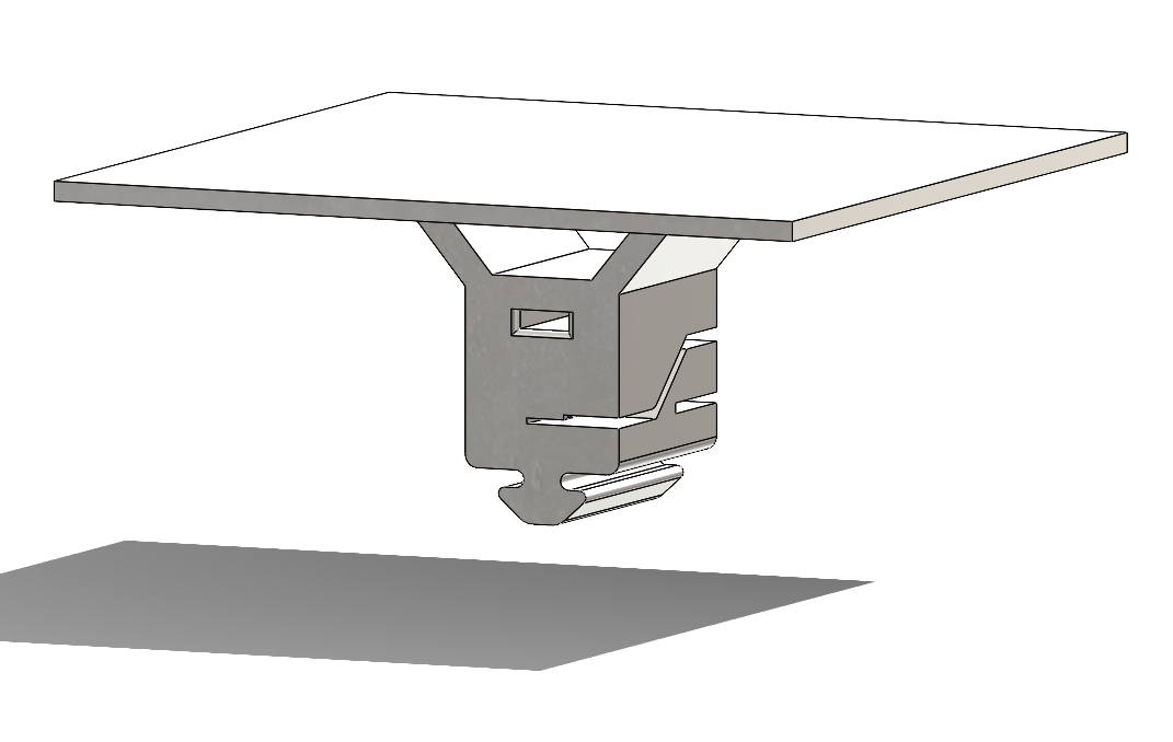
A computer-aided design (CAD) drawing of a metallic structure with a flat square top and a complex central support, casting a shadow below.
A computer-generated model of a partial building or structure with a small window, a sloped interior space, and a curved base.
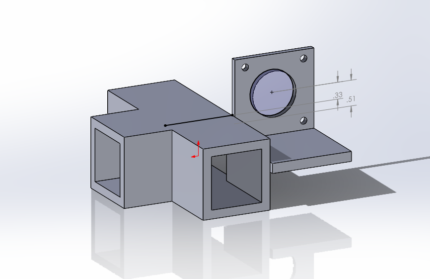
Computer-aided design of a metal mechanical assembly with multiple hollow cubic components and a mounting plate with a circular hole.
3D model of a metal component with holes and cutouts, featuring a flat base, vertical walls, and slots.
3D illustration of a metallic number one with a hollow square at the top, casting a shadow to the right.
A 3D model of a black triangular metal plate with five holes and three cylindrical pins attached.
A 3D-rendered metal mechanical part with a central circular cutout, four smaller holes around it, and a protruding horizontal extension at the bottom.
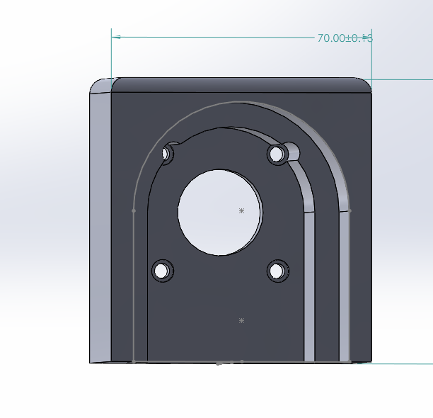
A technical CAD drawing of a metallic component with a central circular hole and four smaller holes, dimensions approximately 70mm in width.
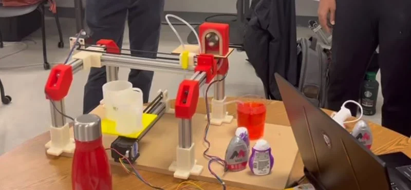
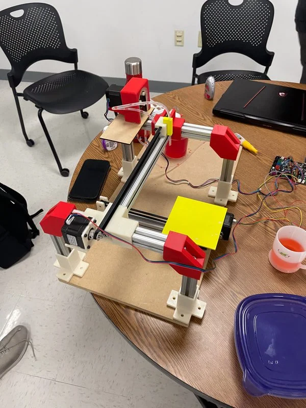
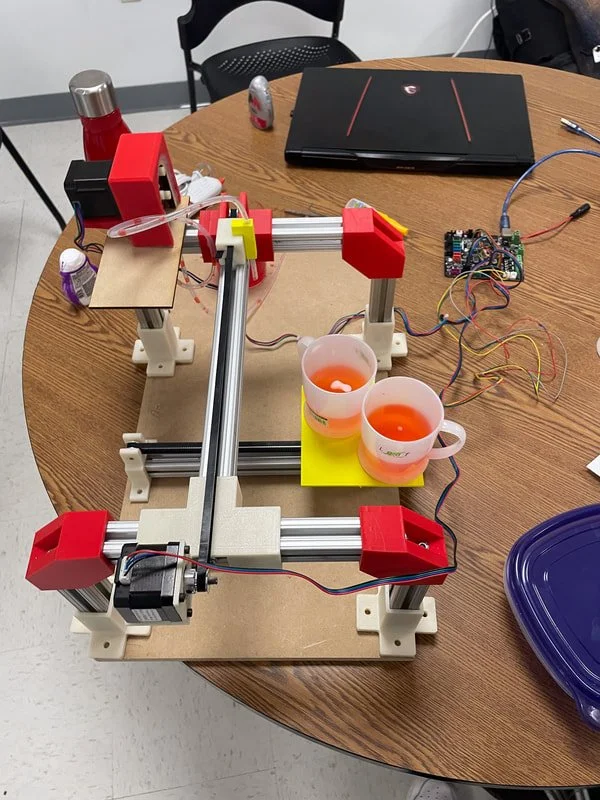
Final Build!
Here is the finished product! All the corner pieces and leg pieces are screwed into the bars to create a sturdy frame. The bottom x-direction has the motor and holder all set up, and the y-direction up top has the slider, nozzle, and motor all connected. The peristaltic pump was situated on a wooden block, which was glued to one of the corner connectors. A silicon tube was run through a cup of red liquid, the pump, and finally through the nozzle on the slider.
All motors were connected to the Arduino Mega and powered by a 12V source. G-Code was used to move the x and y motors to pour drinks into two cups diagonally across from each other. I am very happy with the product, and I am thankful to my teammates for working hard with me to create this.