Automated Manufacturing Assembly Line - BagMate
My first experience with robotics and CAM programming!
Introduction
For my ME:345 Automated Manufacturing class, our final project was to use the Automated Design and Manufacturing Lab at the BU machine shop to make an assembly line for our own custom product. The product would be made of 2 machine pieces of HDPE or acrylic, and must be assembled using robotic arms. Thus, we had to use CAD, CAM, and robotic programming software to create an assembly line system and physically test it in real life! I worked in a team of 5 to complete this project over the course of a semester.
My role
I was in charge of the CAD and CAM programming for the project, and then I was assigned one robot that I had to program. This robot would need to take stock material and put it inside a CNC before machining, and then take out the piece after machining and put it on the conveyor belt.
Skills Utilized
SolidWorks CAD • SolidWorks CAM
Engineering Drawings • Design for Manufacturing
3D Printing Integration • Prototyping & Assembly • CNC Machining
Timelapse of our assembly line for our 2 parts!

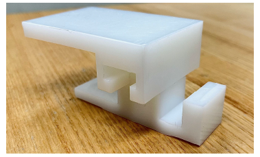
2 of our completed parts!
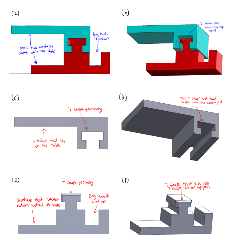
CAD Design
We designed 2 parts that feature a T-slot mechanism. This approach allowed the top and bottom parts to slide together securely, eliminating the need for the snap-fit that was difficult to machine. The T-slot design provided a stable and robust connection, significantly reducing the risk of tilting or instability during the milling process. This design resolved many of the machining issues we experienced in previous lab assignments and resulted in a much more durable product. The T-slot mechanism created a stronger connection between the parts, making BagMate more capable of handling the weight of a bag without snapping or coming loose. Additionally, the assembly process was easy and reliable, as the sliding mechanism offered a smooth and secure fit.
The parts are made from HDPE (high-density polyethylene). There are set stock sizes that we were allowed ot use for machining, and so our design revolved around the thickest stocks we could find, which is 1” thick. There are many chamfers placed on the design because a robot will be pushing the parts together, and so misalignment will be corrected by the angled openings. There is also a table of tolerances given to us that allows us to plan for the error in our parts. In the dimensions for the parts below, I followed this table and accordingly set the decimals in my drawing to correspond with the error predicted.
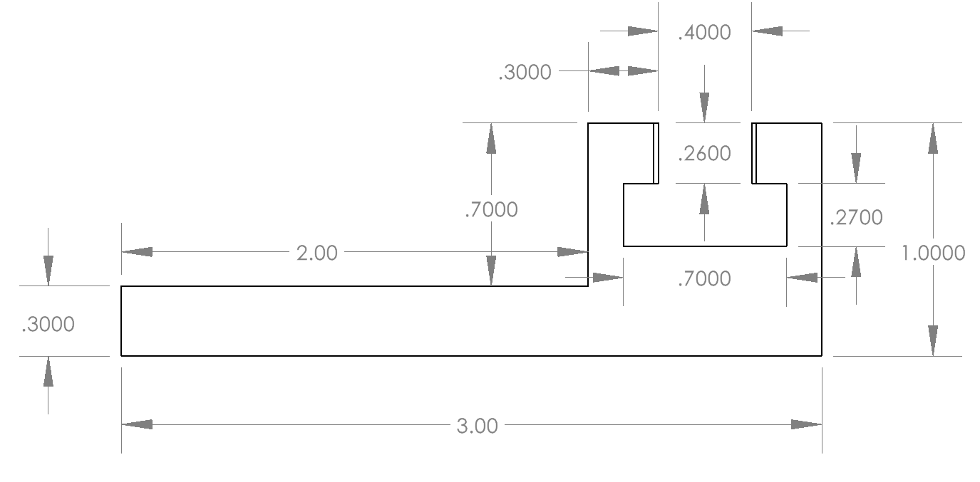
Top Part Side View
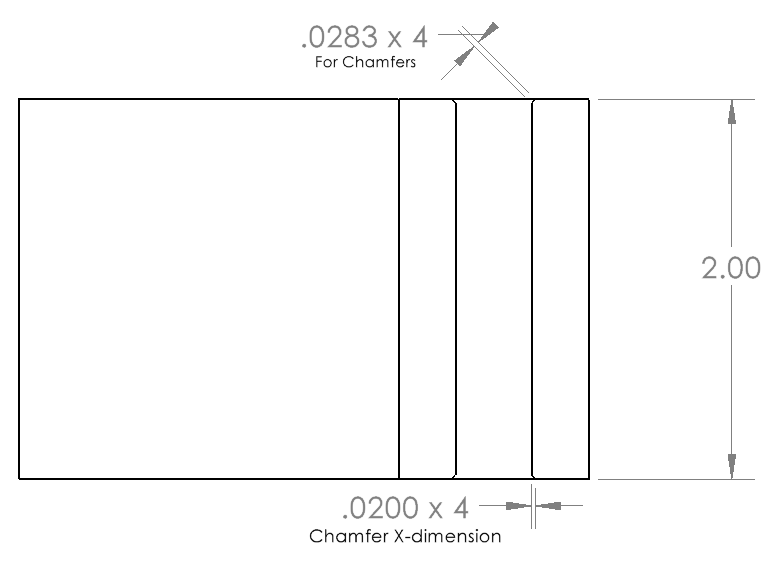
Top Part Top View
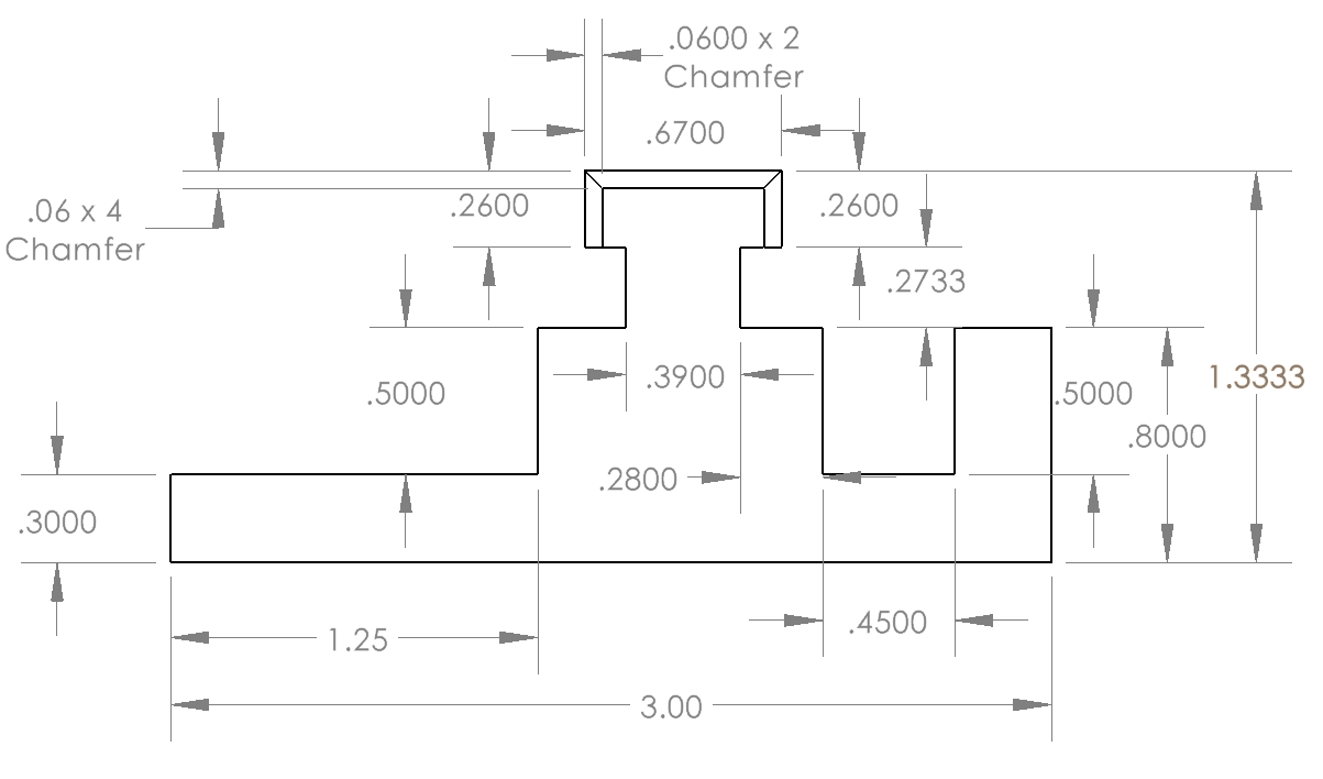
Bottom Part Side View
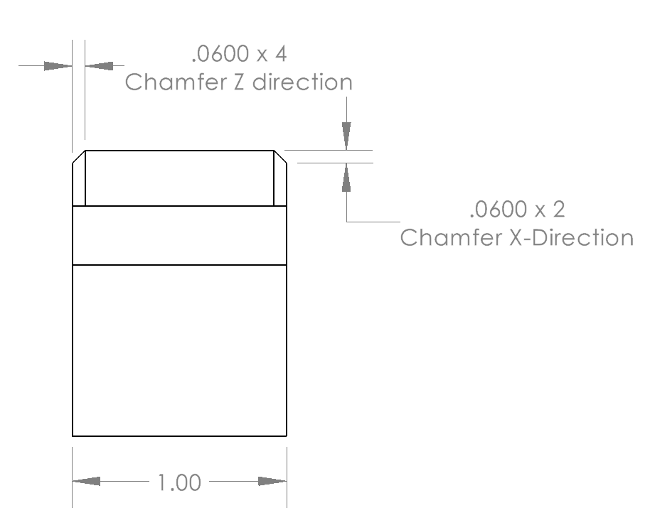
Bottom Part Front View
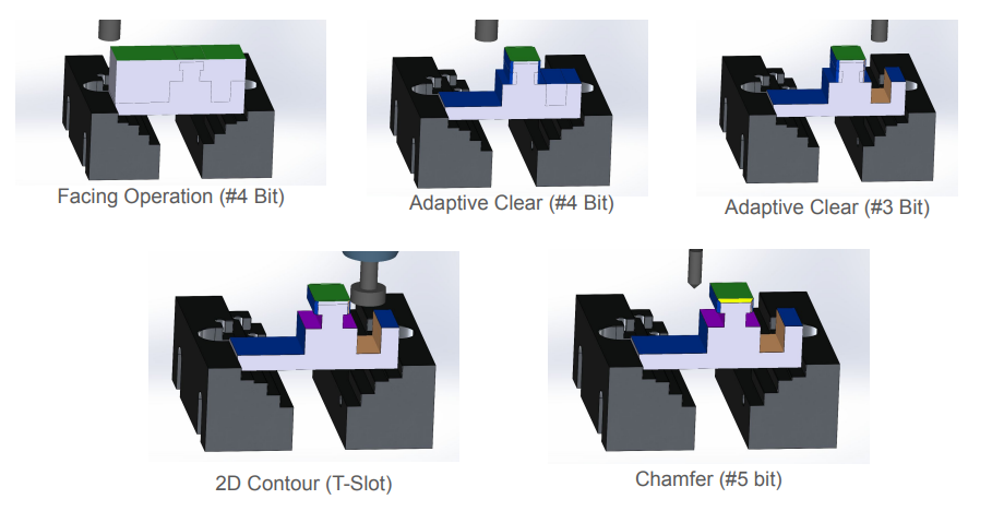
Top Part Machining Processes
Bottom Part Machining Processes
CAM Programming
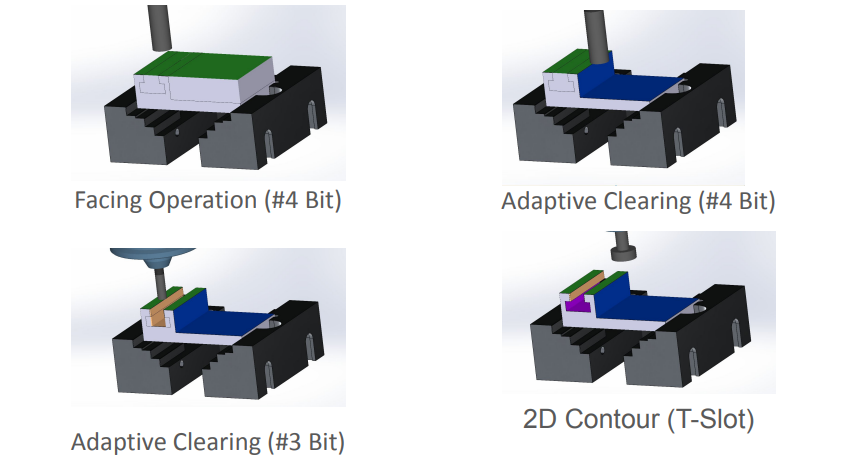
Once the CAD for our 2 parts was finalized, I started creating the CAM program for the parts to be machined in the CNC mills at BU. I used 2024 SolidWorks CAM for the programming of the project. There is a vice inside the CNC mill that we were given the model of, and there are also set stock sizes of HDPE that we could use to machine. A set list of 8 drill bits was given to us, where 5 drill bits were for regular axial and radial cutting, 2 bits were used for chamfers, and 1 drill bit was used for T slotting.
For the 2 parts, I utilized a lot of different milling operations. For the top part, I used the largest drill bits for facing and adaptive clearing, and then utilized the T-slot and smaller drill bit for the channel. The bottom part featured a lot more tricky operations, and it was thinner, so I had to be careful with the speeds and large drill bits because it could tip the part over. I utilized the large drill bits for facing and adaptive clears for most of the features, then I utilized the T-slot and chamfer bit for the final features.
Machining
Top part being machined with my CAM program! The 3d printed insert I printed is nestled in the gap of the vice to space the part into the middle
I had to work with 1 of my teammates to configure the CNC mill to machine the top part. We had probably machined 30 test pieces to try and get it to work! What was going wrong was that first, going at 100% feed rate and spinning at 100% spindle rpm made the part constantly tip over and get loose inside the vice, and so the cuts would be very off. The solution for us was to decrease the feed rate and RPM to around 70% of the normal settings. There was then a 90% success rate with parts after this change, but our cycle time increased from 5.5 minutes to over 7 minutes, which would not be great for the assembly line.
In the vice, there is a 3d printed part that I made to act as a wall for the stock to rest against. That is because the vice had corners cut out in it’s original wall to facilitate more complex cutting, but these corner cuts hurt our machining processes because less surface area for the vice to grip meant the part would loosen more easily. I made a 3d printed spacer so the stock could rest against the full walls of the vice in the center, and this fix drastically improved the success rate of our part alongside the changes in spindle speeds!
Robot Programming
Programming the robots was the most fun part of the project! I learned about programming the robots in waypoints, and how to utilize moveJ and moveL commands to dictate the path of the robot end effector. There are 3 robot arms used in the project, where 2 are used for loading and unloading parts from the CNC mills, and 1 is used for assembling the parts. I programmed 1 cobot for the CNC mill, and I assisted with the assembly programming of the cobots. I apologize for not having any slowed-down footage, but hopefully the footage illustrates the amount of programming we did with these robots! We used teach pendants and had around 40 commands for each robot to run through to accomplish their tasks.
The robot I programmed for the CNC mill had to take a stock piece from an inventory rack, then use a jig to position the stock to be in a precise location in its grippers. Then, the robot arm had to take the stock piece, place it inside the CNC mill vice, and then push the piece so it is securely in the vice. The robot then moves out of the CNC mill, waits for the machining to finish, and then has to go back inside the CNC to take out the stock piece, and then put the stock piece on the conveyor belt carrier.
Timelapse of the assembly cobot taking the parts from the conveyor belt and assembling them!
The cobot I programmed is taking the stock from the inventory pile and placing it in the CNC. I then monitor the CNC running my CAM program. The cobot takes out the part after machining and places it on the conveyor belt carrier for transport to the assembly station.
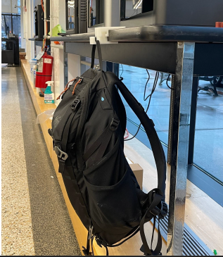
Finished Parts and Final Words
The parts were machined, and the finished product was able to hold a backpack! With our automated assembly line, we created 10 pairs in total, which we distributed to our classmates after our presentation. It felt amazing to see the complete parts after completing the whole designing and machining processes. I had to do the CAD, CAM, robot programming, and physical machining of the parts all in one semester! The robotics introduction was my favorite part. I have definitely found a new passion for robotics after interacting with and witnessing the cobots from Universal Robots.