Finite Element Analysis
Highlights of the FEA portions of my projects!
Vibram Transparent Inclinable Walkway
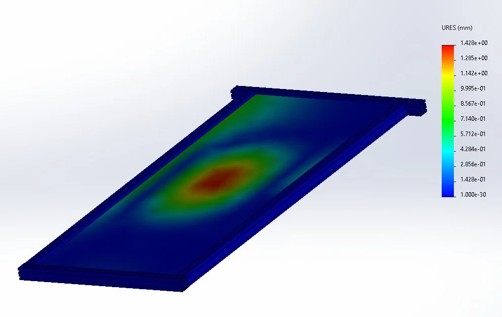
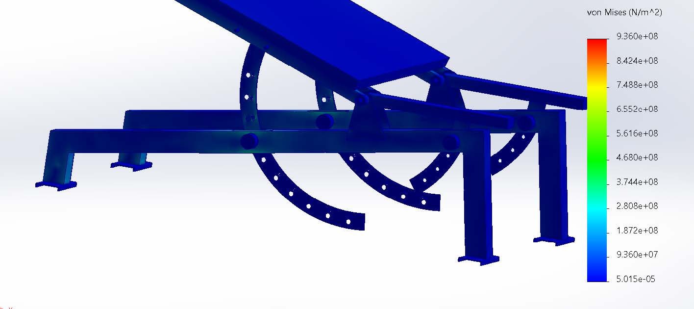
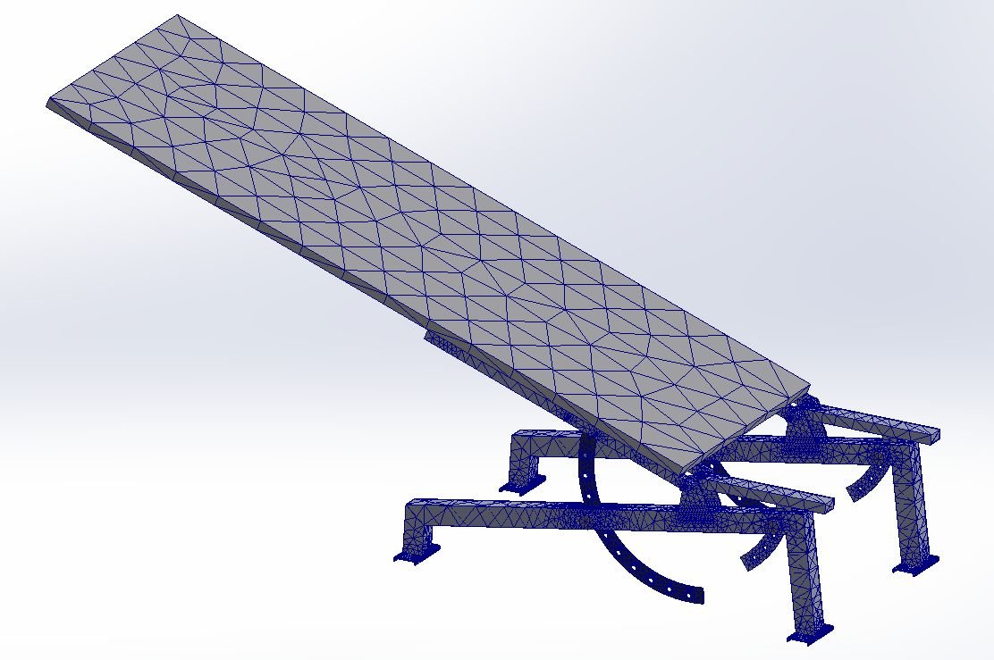
I led the structural simulation work to ensure the walkway would safely support a user at maximum incline. I used SolidWorks Simulation to run multiple FEA studies on the acrylic plate, aluminum frame, and gym bench under a 1000-lb load case. The forces were usually input onto a small rectangular section that is approximately the size of a human foot on different parts that would mimic the force concentration of a walking motion. These simulations helped us determine the optimal acrylic thickness and the strength of the 8020 bars and gym benches. I had to learn how to refine mesh strategies and boundary conditions so our results better reflected real-world scenarios without taking too much time. Even though they were static simulations, we ensured that we used an adequate factor of safety to compensate.
To go in depth about the acrylic results, we found that the acrylic thickness needed for safe use (factor of safety of 2 for a load of 1000lbs) is 0.42 inches. However, we could only choose acrylic in increments of 0.25 inches, so the available choices for us were 0.5in, 0.75 in, and 1in thick acrylic. I then tested deflection for each acrylic thickness and compared each plate’s results to the cost and weight. Weight is important because a lighter plate would be easier to lift up and down for angle changes. After comparing the different parameters, we ended up going with 0.75-inch thick acrylic plate.
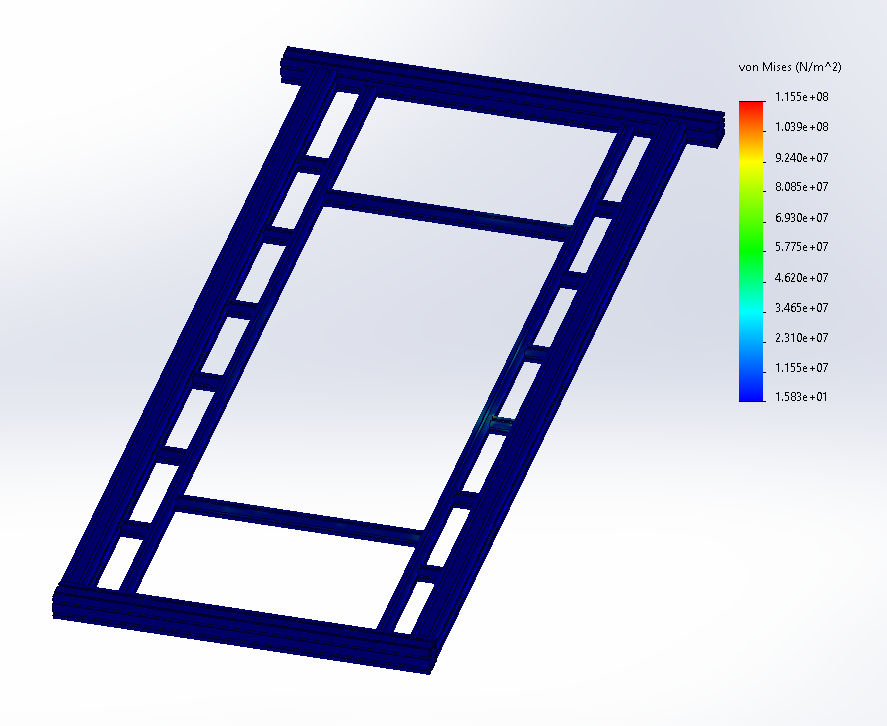
I then tested for the integrity of the 8020 beams in the frame. The frame was composed of 2020 and 1010 aluminum beams made of AL 6061-T6. These t-slots were tested under distributed loads in the FEA in the area of 200 kPa, or 40 psi.
We tested the gym benches and pins just to check what loads the pins could take, just as a preliminary way to check the failure modes. We realized the pins, if used alone as the sole method for securing the acrylic and frame, would endure loads 5x their ultimate stress. So then we started developing the safety struts.
Peristaltic Pump
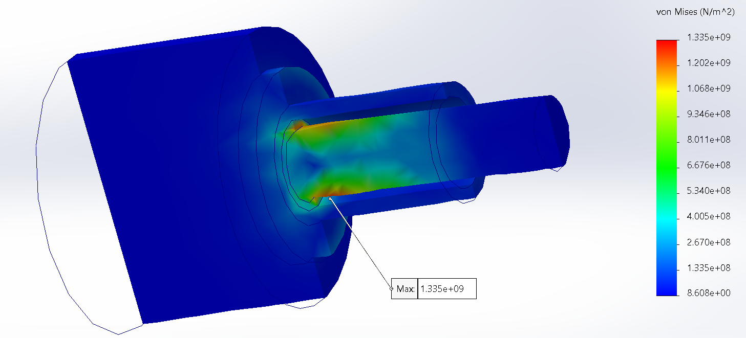
I decided to make the pump parts out of acrylic for the beautiful look of the parts. I acknowledge that acrylic is a very brittle material with low tensile strength and shear strength, so it is probably one of the worst materials to use for a pump where there are relatively high forces. I thus calculated the shear stresses that would occur in the pump from compression of the tubing and found that the forces would be in the range of 30 kg on each node of the triangular part. I did a crude FEA analysis to test out how much the acrylic could take, and surprisingly, the tests showed that the part is able to take those stresses with a Factor of Safety of 2! But I know that this is not a conclusive result and I will do some trials and testing in real life on the physical model to see if the parts can hold up. I will order multiples of the parts just in case of failure!

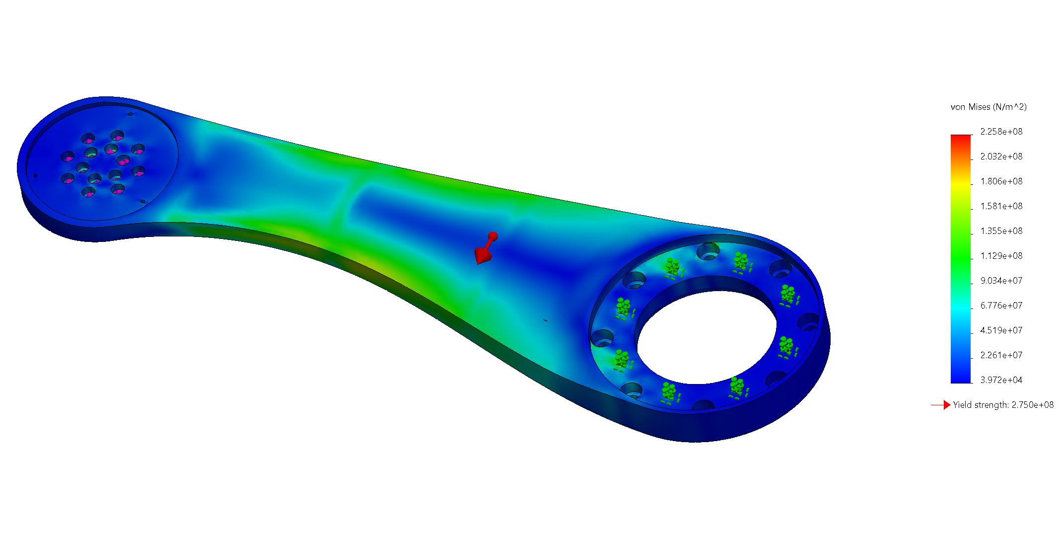
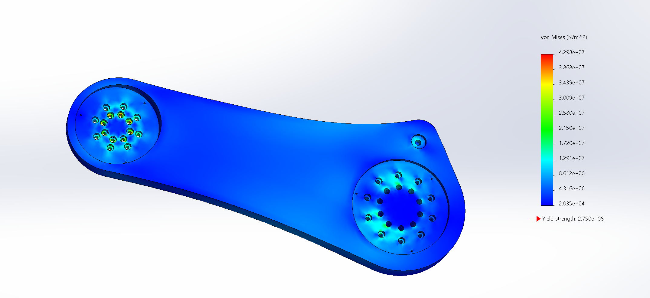
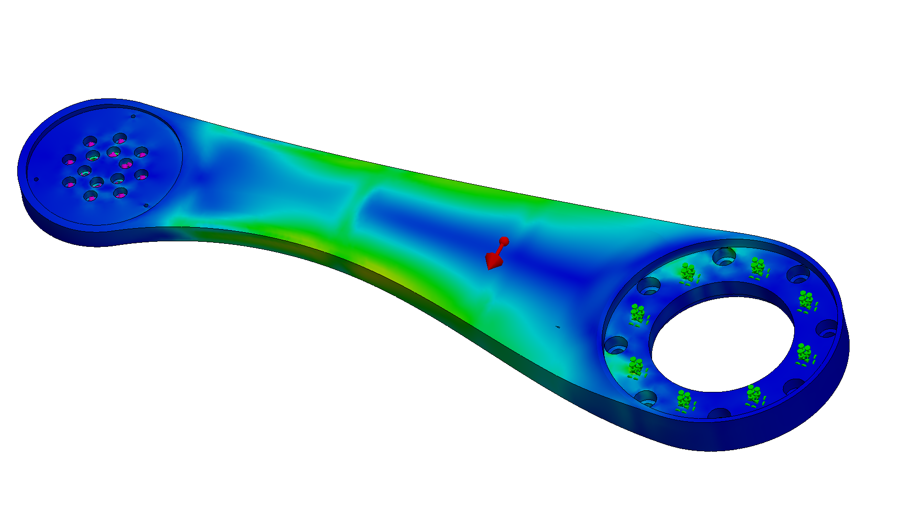
Five Axis Robot Arm!
The arms of the robot will be made out of AL 6061, and the gearboxes will be made of 304 Stainless Steel. The gearbox of Joint 2 will experience extremely high loads, and thus it is being made out of EN 24 Alloy Steel that is heat-treated to achieve an HRC 45 rating.
I first conducted static FEA simulations of the arms of the robot, since I was worried that the holes would shear off or deform from the high torques. For input forces, I would always put the predicted torque forces in the screw holes, and I would also put a directional force for gravitational and acceleration loads. I would test with a Factor of Safety of 2, with the applied load being around 4x the static gravitational load of the components. The two components were able to pass with flying colors. I might have gone overkill in ensuring the parts could handle the loads! Even if there is a lot of weight, it would cost much more for me to actually add operations to carve out the arms, and so I left it as a solid piece.