Peristaltic Pump Project!

Introduction
I had made a 3d printed peristaltic pump in my ME 360 - Electromechanical Design class as part of a 2.5 degree-of-freedom drink dispenser project. I loved the beauty of the device and how easy it was to make, and I wanted to create a more professional version to use for my plant at home. Thus, I designed and ordered custom CNC parts to complete the build
Skills
SolidWorks CAD • Design for Manufacturing
Engineering Drawings • Finite Element Analysis
CNC manufacturing • Prototyping & Assembly
CAD Design
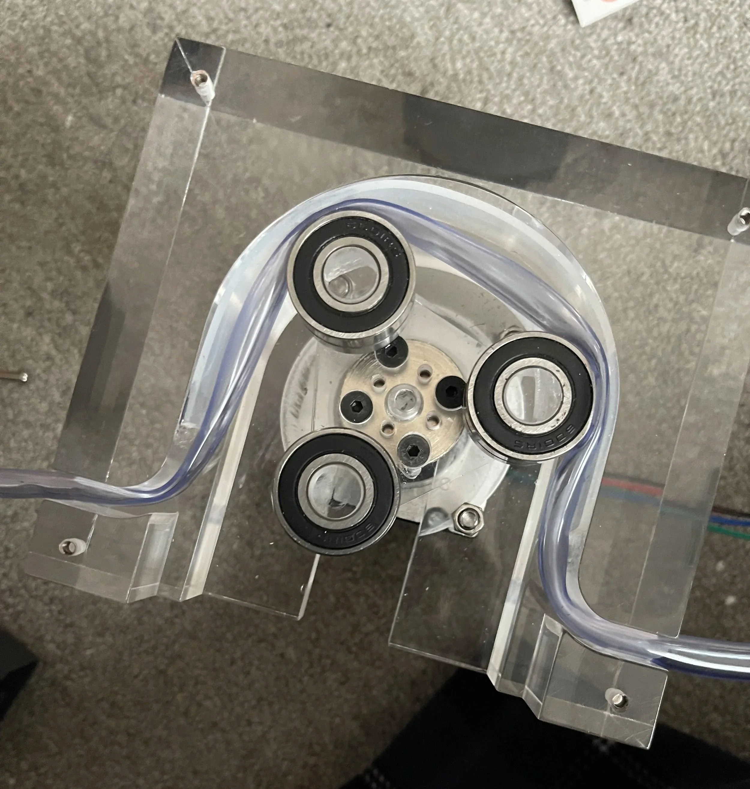
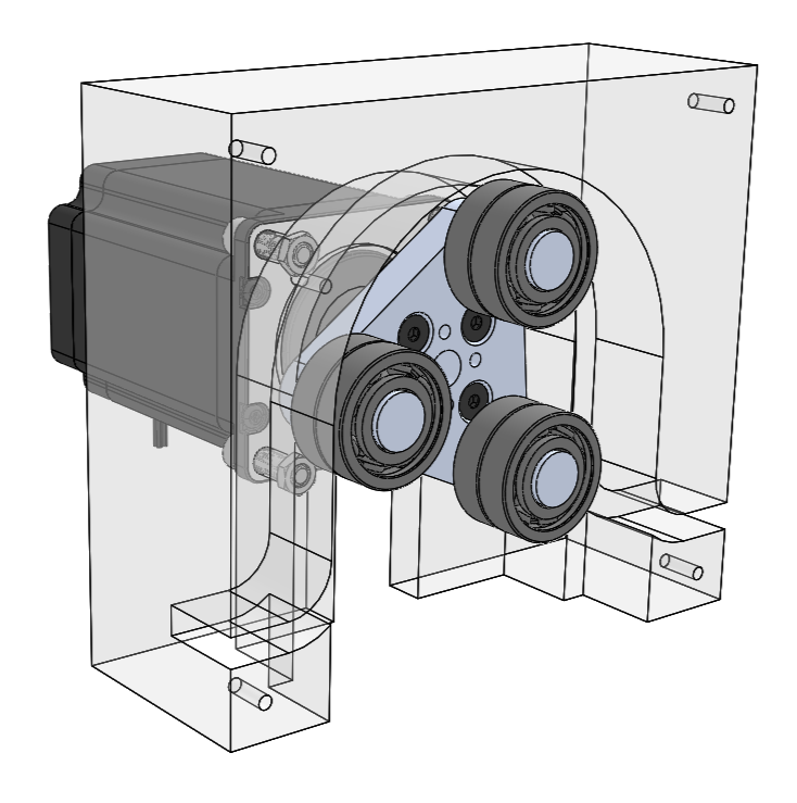
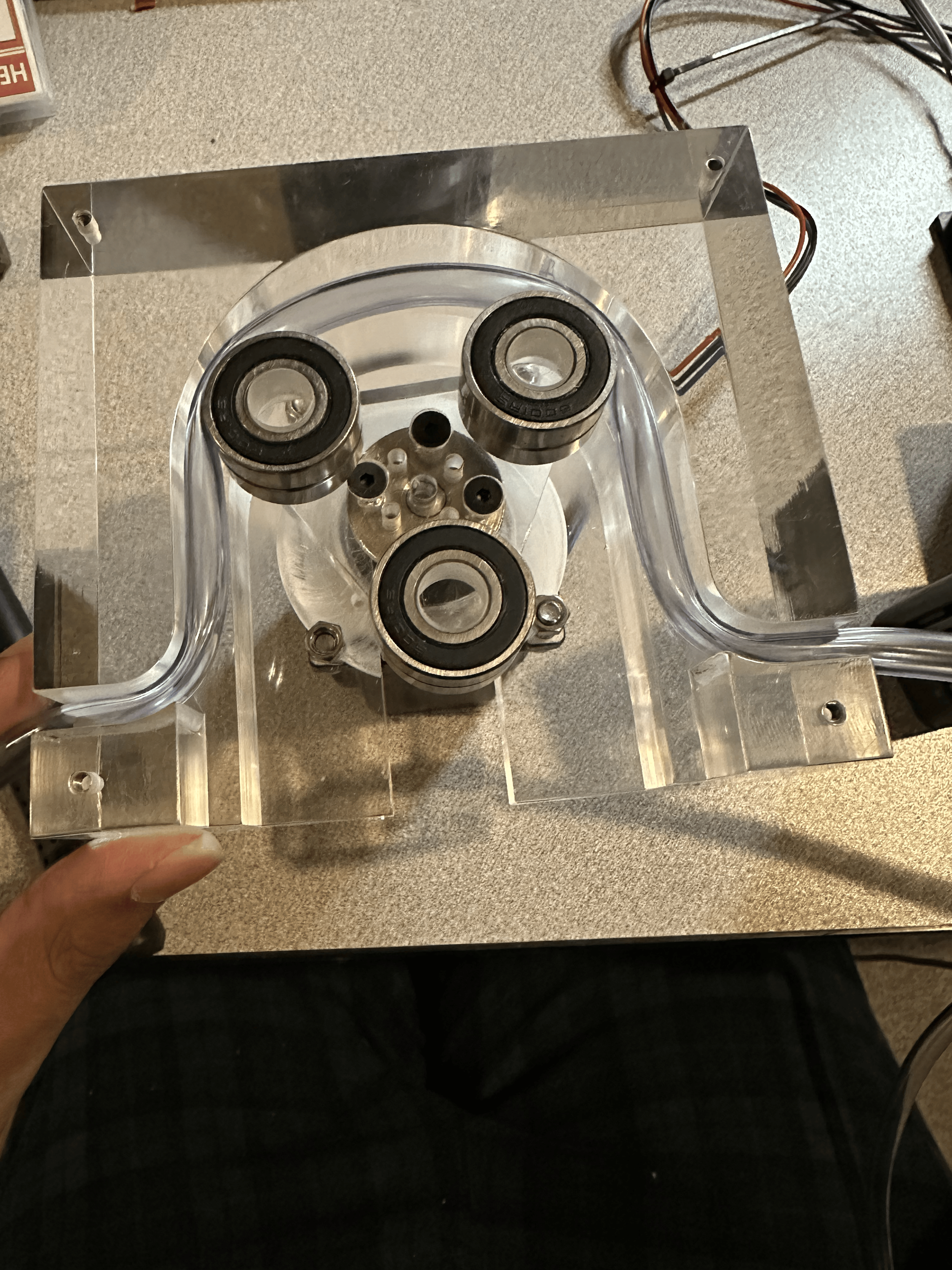
I recreated a simple peristaltic pump design that is commonplace in professional products. Usually, a strong stepper motor is attached to a frame, and revolves ball bearings in a circle to squish a tube in a circular motion. The revolutions of the ball bearings push the air inside the tube and create a vacuum force in its wake. This allows for a pump that does not need priming and is extremely precise in the amount of liquid dispensed.

Finished 3d Printed model!
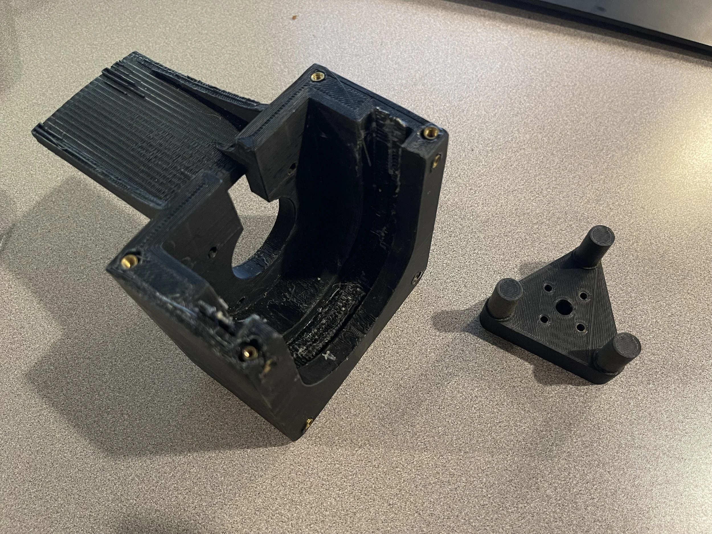
Closer look at both parts. I know it is a little messy, I did not make great supports with my printer so it is rough, and I glued gt2 belts for better compression of the tube and it got everywhere!
3D Printed Prototype
I had made a 3d printed peristaltic pump concept model in my dorm room to try and find ways to water my plants on the windowsill. The pump worked well! Surprisingly, the 3D printed frame and bearing holder did hold up to the forces needed to make the pump work. I was printing the parts with my Elegoo Neptune 3 using around 75% infill so the parts would not break. I got a lot of rough surfaces because of tough supports, and I glued some rubber gt2 belts to the inner lining because I could not get a good squeeze from just the bearing holder. I also laser-cut some acrylic and put heated inserts in the print to make the product look better.
Drawings and Machining Plans
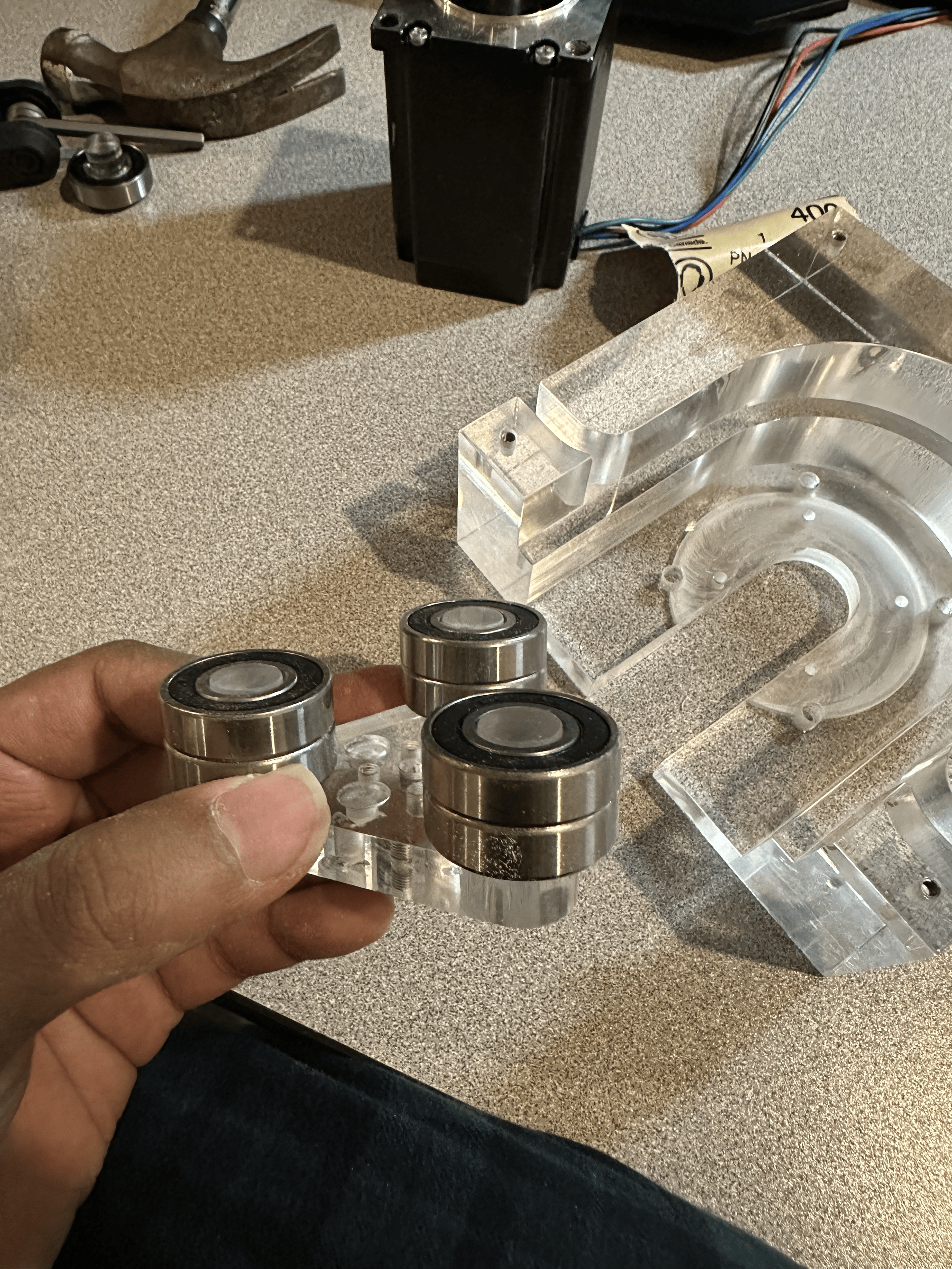
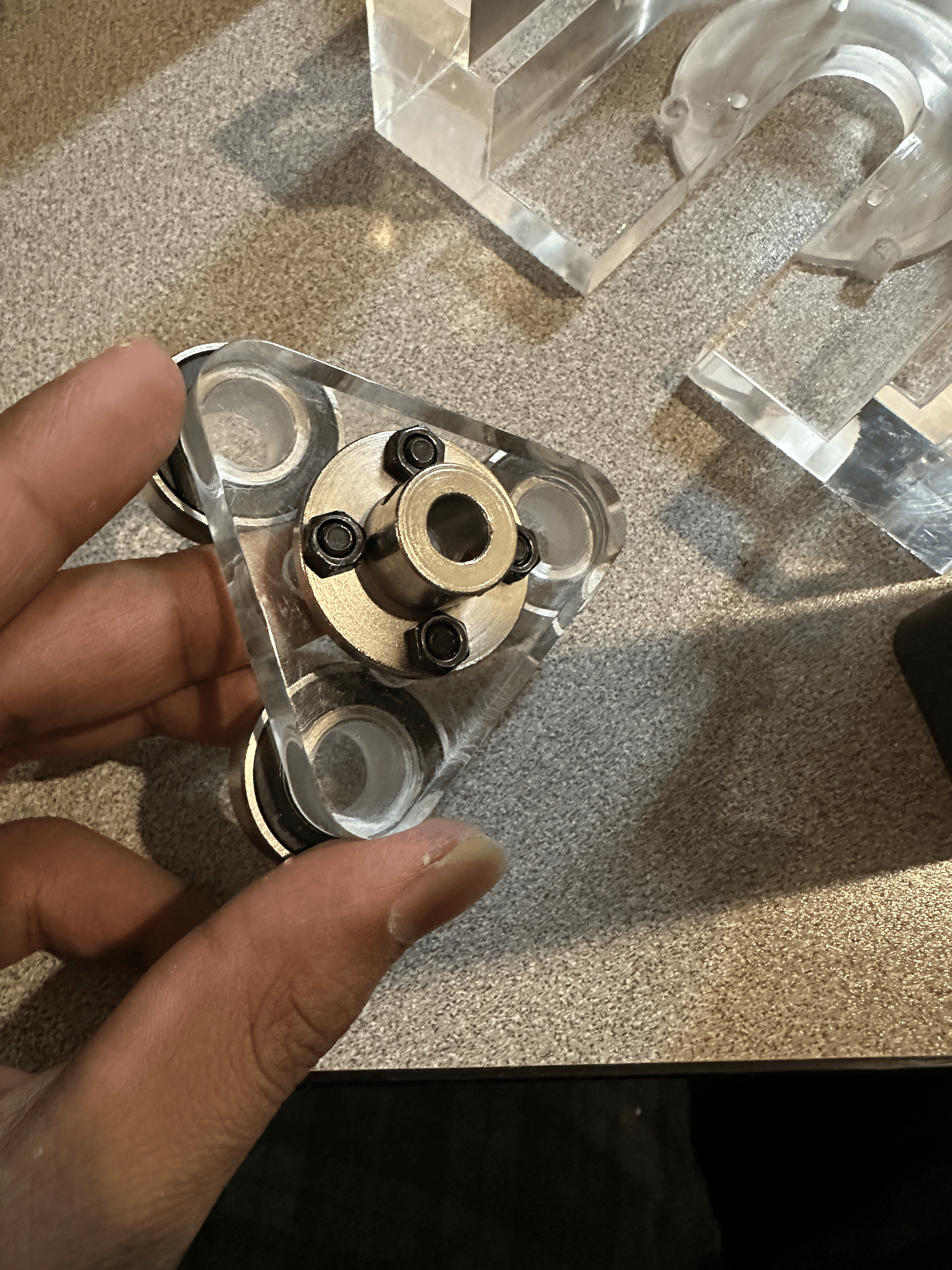
There are only 3 parts that need to be machined: the frame, the ball bearing holder, and the lid. I created drawings for each part, and had them custom-machined out of acrylic. The tolerance was not very tight; I used a standard 0.1mm bilateral tolerance that the machine shop used. I planned to use acrylic for the parts to allow for a clear appearance for the pump.
I made the design such that the ball bearings and the frame of the device should have a 3mm gap when the pump is in motion, and the tubing will have a 1mm gap in the center when it is compressed. I could add a 3d printed part or film to the outer edge of the wall to reduce this gap later. My thinking was that it would always be easier to add something to the frame to make the tube compression larger than to enlarge the gap and make the compression smaller.
Short FEA
I decided to make the pump parts out of acrylic for the beautiful look of the parts. I acknowledge that acrylic is a very brittle material with low tensile strength and shear strength, so it is probably one of the worst materials to use for a pump where there are relatively high forces. I thus calculated the shear stresses that would occur in the pump from compression of the tubing and found that the forces would be in the range of 30 kg on each node of the triangular part. I did a crude FEA analysis to test out how much the acrylic could take, and surprisingly, the tests showed that the part is able to take those stresses with a Factor of Safety of 2! But I know that this is not a conclusive result and I will do some trials and testing in real life on the physical model to see if the parts can hold up. I will order multiples of the parts just in case of failure!

Building!

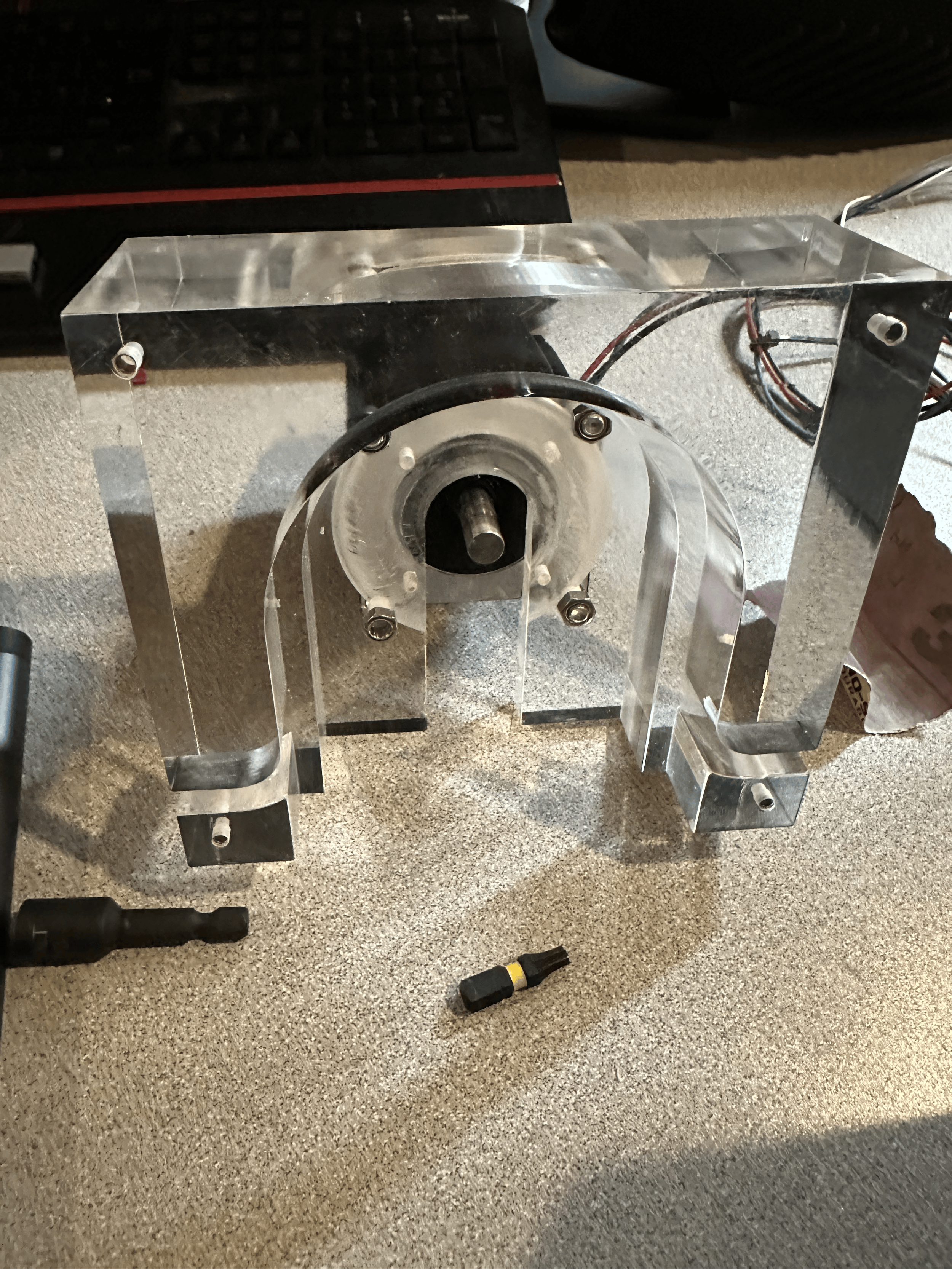
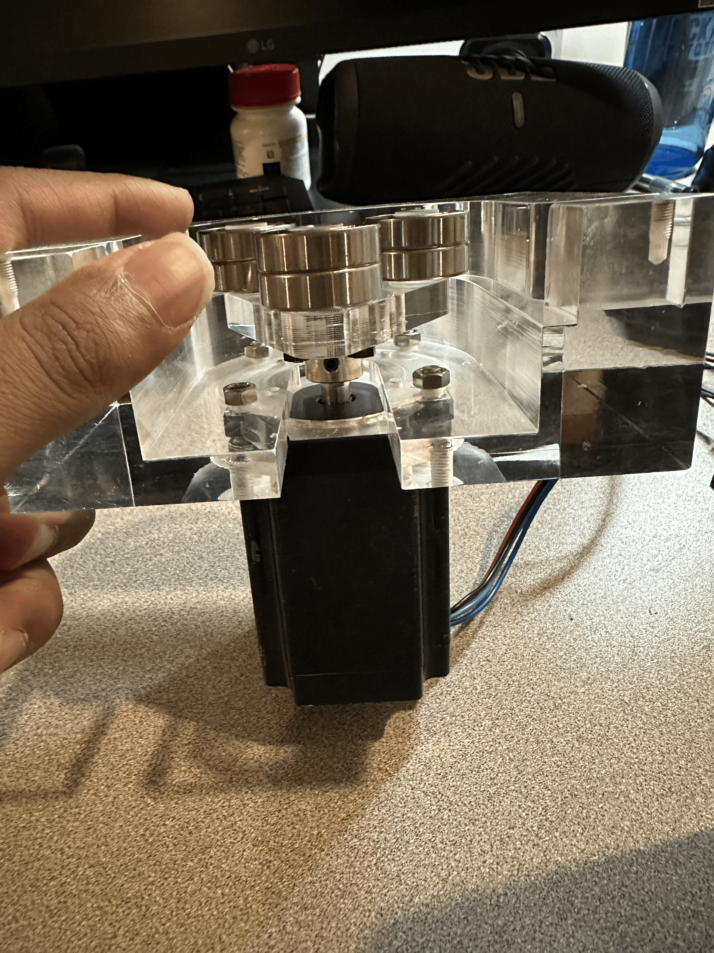

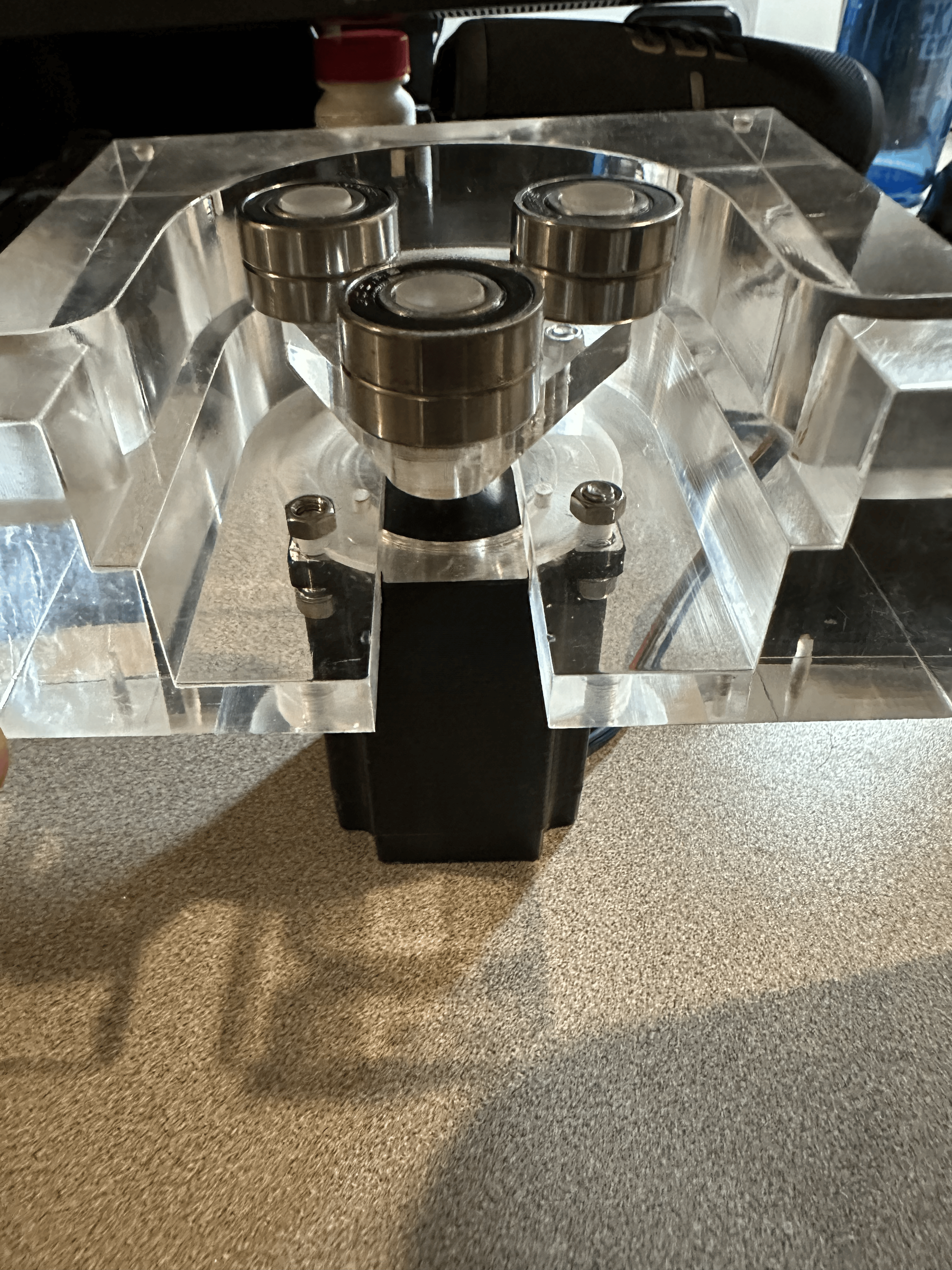
Final Build and Reflection
Here is the finished pump! I am able to just go to my computer and press a button with my Arduino to water my plant! In the future, I will create a physical controller for the device and make an apparatus to water multiple plants with this pump.