5-Axis Robot Arm!
This project is currently in the machining stage and will hopefully be ready in June 2026!
Introduction
I wanted to make a robot arm for myself after taking an automated manufacturing class at BU. In this class, we used 6-axis robot arms from Universal Robots, and I fell in love with them. I wanted to have a robot arm myself, and I knew I would be more satisfied if I built one from scratch rather than buying one off the shelf. During my internship in India at Sensacore, I developed my design by communicating with machine shops to evaluate drawings, and I eventually ordered the components to be manufactured.
Skills
SolidWorks CAD • Design for Manufacturing
Engineering Drawings • Finite Element Analysis
CNC manufacturing • GD&T
My automated manufacturing group project for the ME 345 class. We programmed Universal Robot Cobots to pick and place polycarbonate parts into a CNC assembly line. This project made me fall in love with robotics and is one of my favorite experiences in my college career! I will make a page for this project soon!
Specifications Overview
Over the course of 4 months, I meticulously designed all the components for my robot arm, putting an emphasis on machineability and ease of assembly. The complete CAD assembly has 450 components and is comprised of over 55 uniquely machined parts! The robot's total reach is projected to be 1.10 meters, and the estimated payload will be 8kg. There are 5 axes of freedom that all have custom-made gearboxes. There are 4 cycloidal gearboxes for joints 1 through 4, and 1 planetary gearbox for J5. The first 3 joints near the bottom are powered by Nema 34 Stepper Motors that have 9Nm and 12Nm of holding Torque. Joints 4 and 5 are powered by Nema 23 Stepper motors that have 3Nm of holding torque each.
The materials for the parts that will be machined are Aluminum 6061, 304 Stainless Steel, and heat-treated EN 24 Alloy Steel. Stainless Steel is used for the gearboxes for its superior hardness and strength compared to aluminum, and hardened EN 24 is used for joint 2 since that gearbox will endure the highest stresses of the whole robot.
360 view of the robot with gearbox internals visible
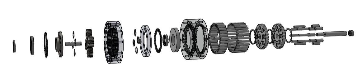
Exploded view of joint 2
CAD Modeling and Gearbox Design
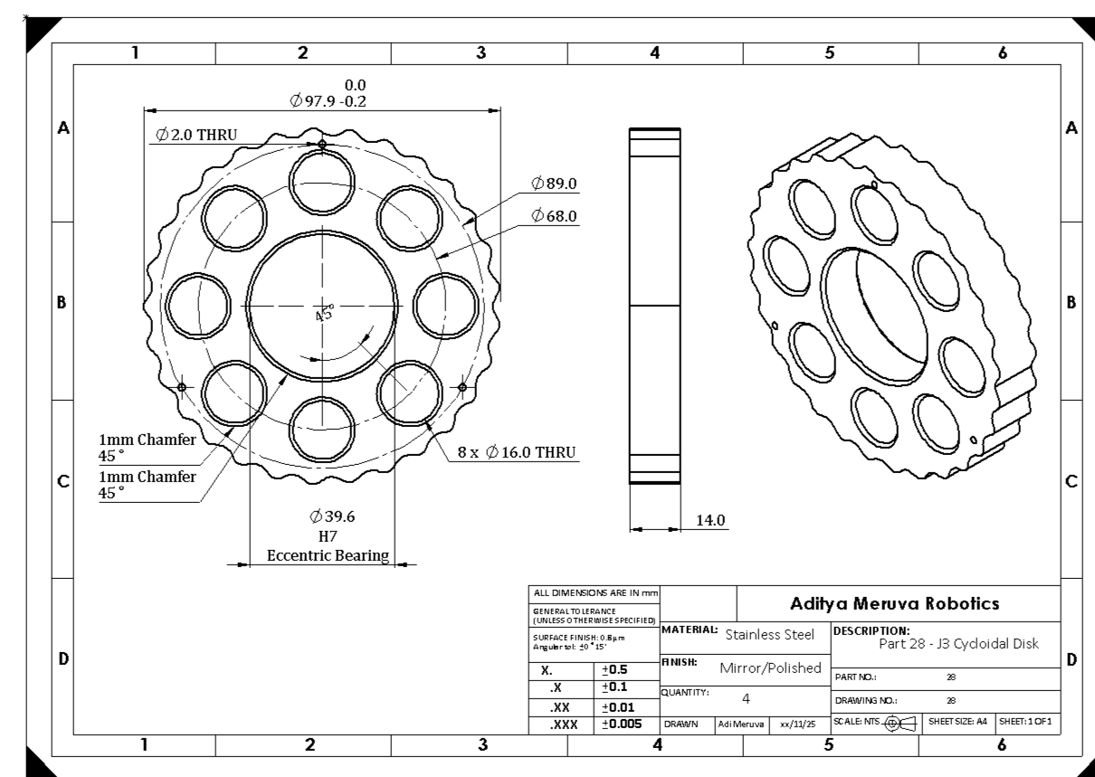
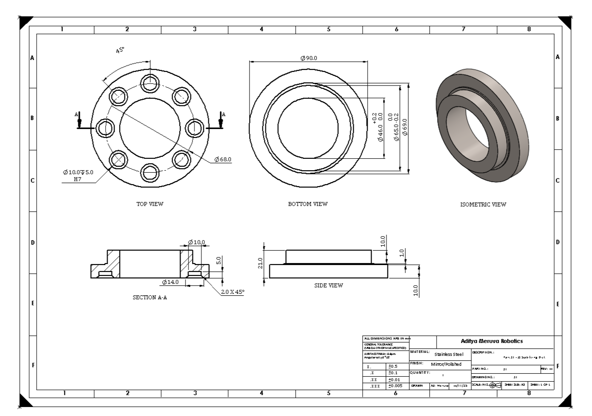
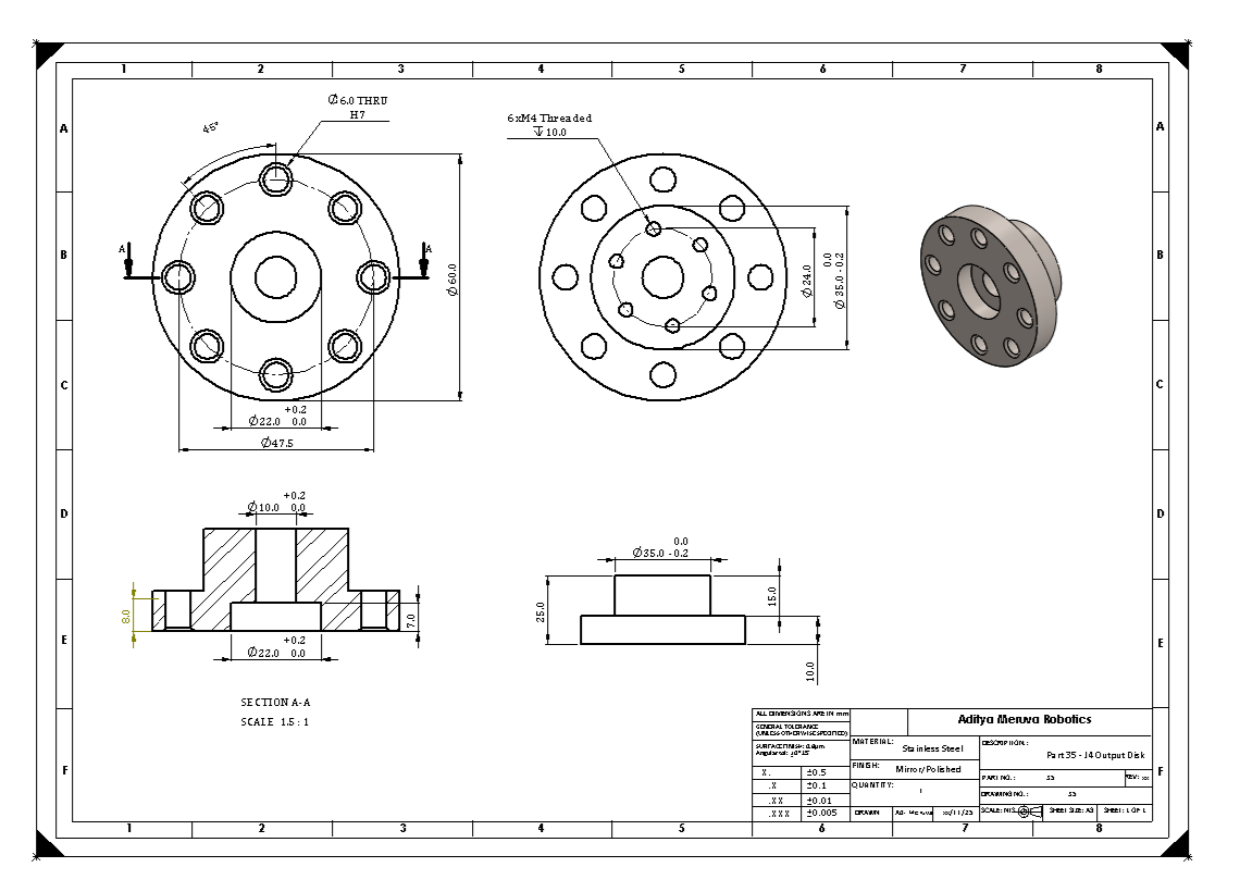
The gearboxes in Joint 1-4 are cycloidal gearboxes with a 25:1 ratio, with Joint 2 also having a planetary stage that makes the ratio into 100:1. Pitcured above and to the side is the CAD model of Joint 2 in both a section view (with some parts hidden) and an exploded view.
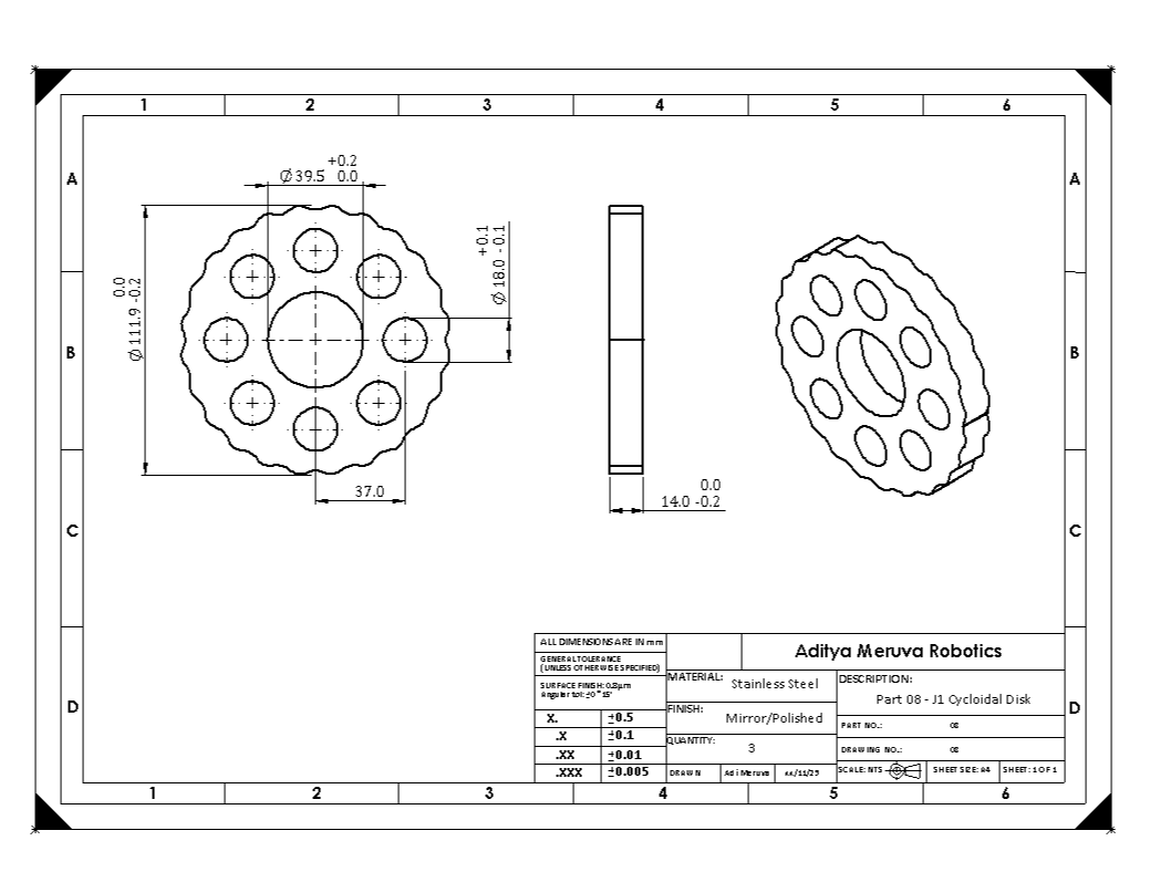
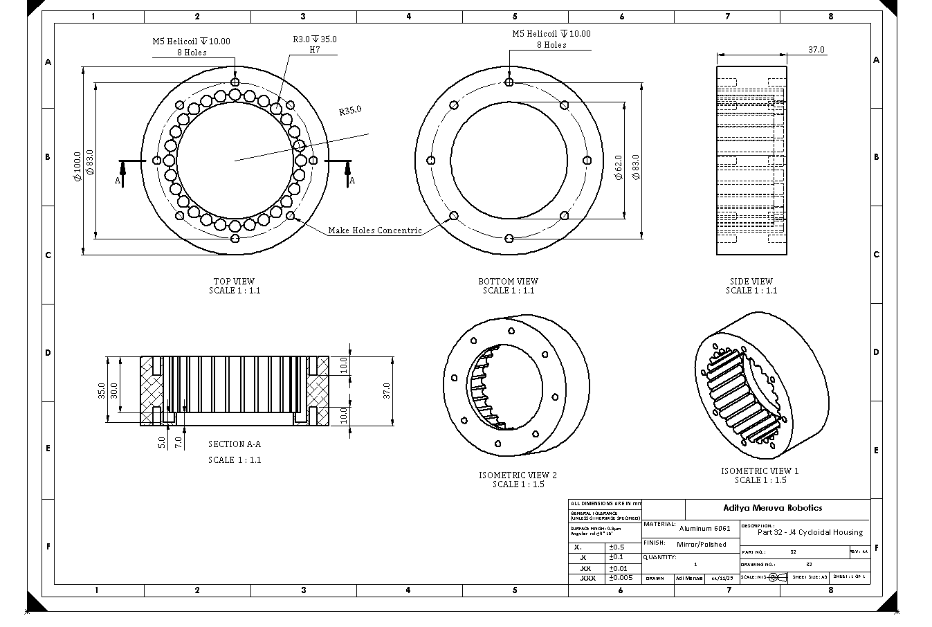
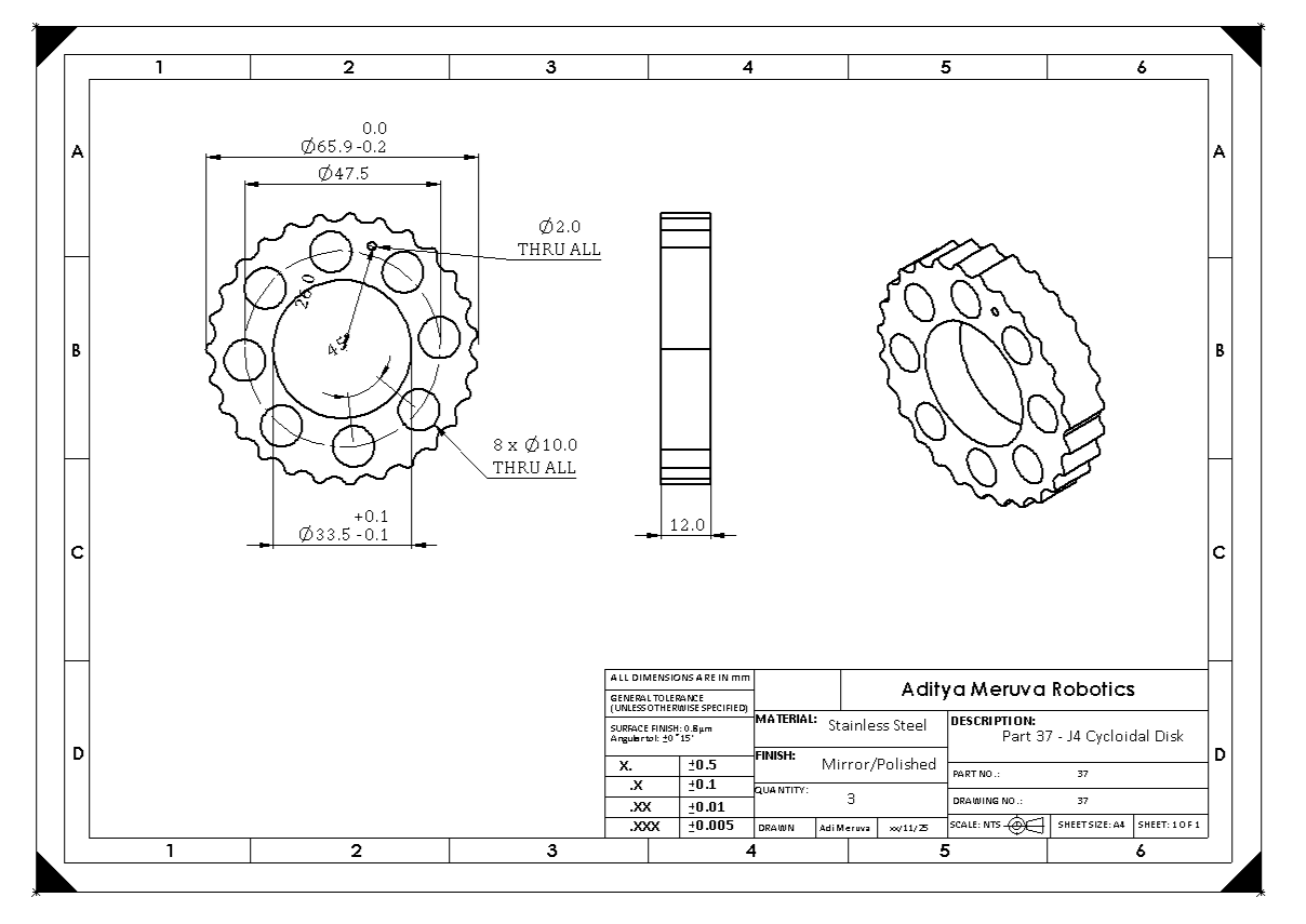
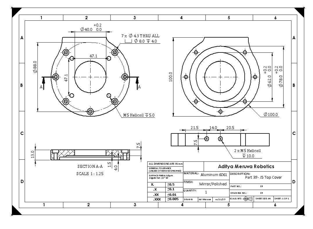
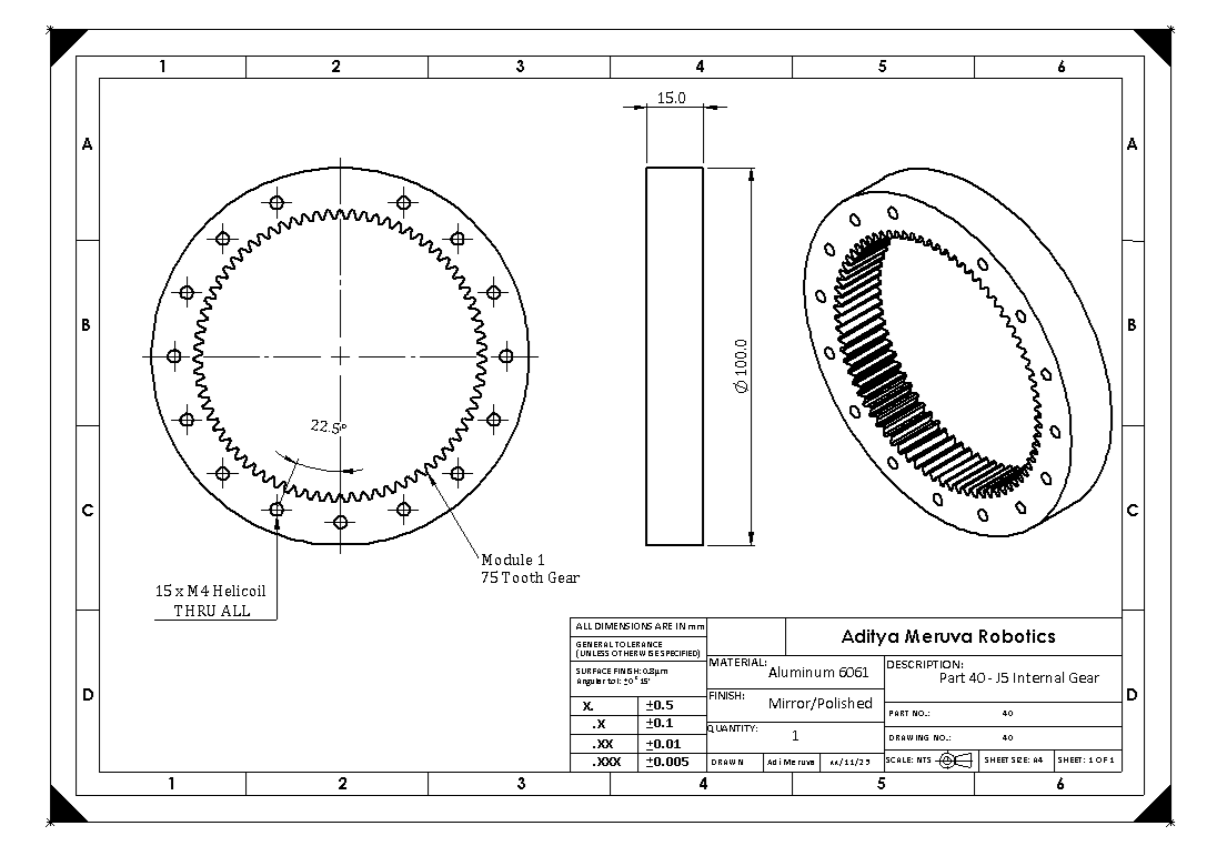
Each cycloidal disk is created using parametric equations, and they utilize eccentric bearings that create a unique oscillation motion. Joint 5 uses a planetary gearbox to conserve weight, since cycloidal gearboxes usually have more mass in the same package than planetary. There will be backlash in the cycloidal and planetary portions of the build, and I hope to do backlash compensation in the code. The housings for the planetary gears in Joint 2 and Joint 5 are going to be made from wire EDM, while the cycloidal housings will use CNC milling. I had to make some design modifications to make sure the products were machineable, such as making the pin holes less tall because the tool heads could not reach those depths.
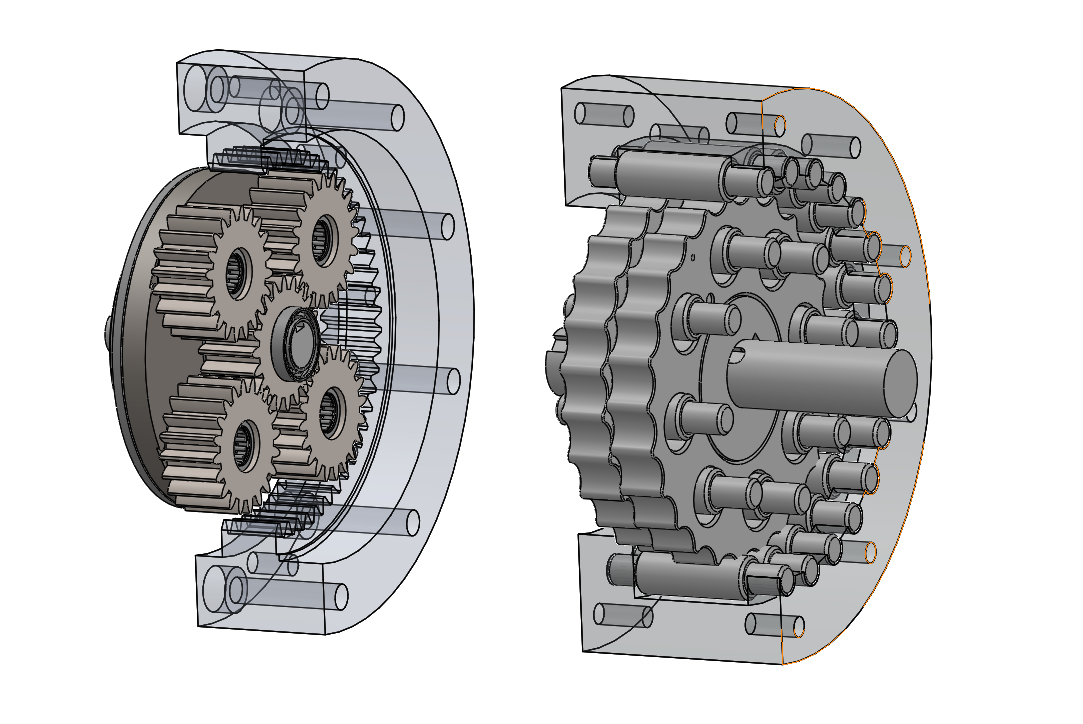
Section view of joint 2 with some components hidden
Finite Element Analysis
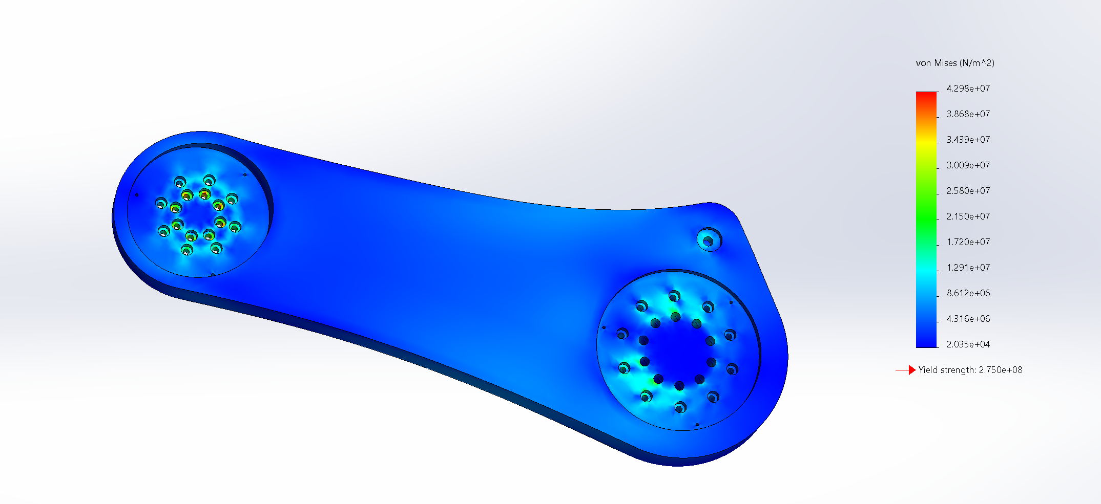
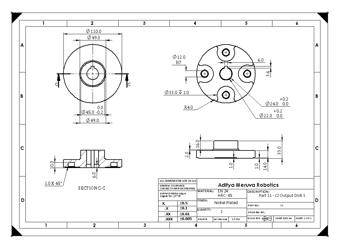
The arms of the robot will be made out of AL 6061, and the gearboxes will be made of 304 Stainless Steel. The gearbox of Joint 2 will experience extremely high loads, and thus it is being made out of EN 24 Alloy Steel that is heat-treated to achieve an HRC 45 rating.
I first conducted static FEA simulations of the arms of the robot, since I was worried that the holes would shear off or deform from the high torques. For input forces, I would always put the predicted torque forces in the screw holes, and I would also put a directional force for gravitational and acceleration loads. I would test with a Factor of Safety of 2, with the applied load being around 4x the static gravitational load of the components. The two components were able to pass with flying colors. I might have gone overkill in ensuring the parts could handle the loads! Even if there is a lot of weight, it would cost much more for me to actually add operations to carve out the arms, and so I left it as a solid piece.
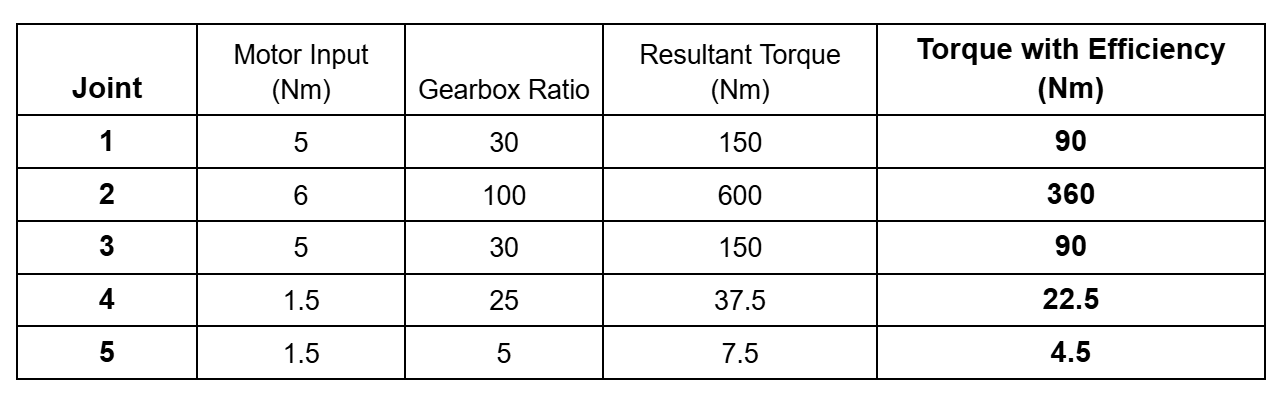
Motor Torque Estimation Chart
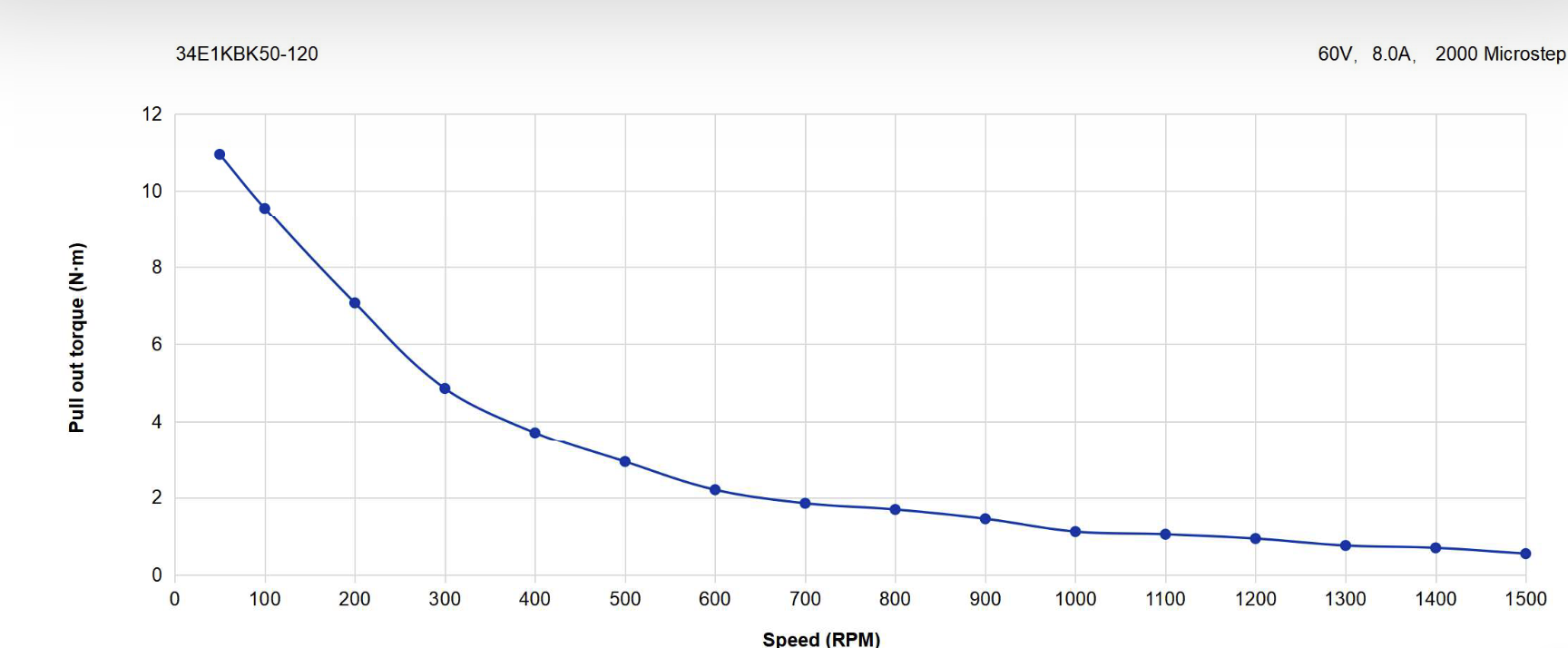
Torque Curve from StepperOnline
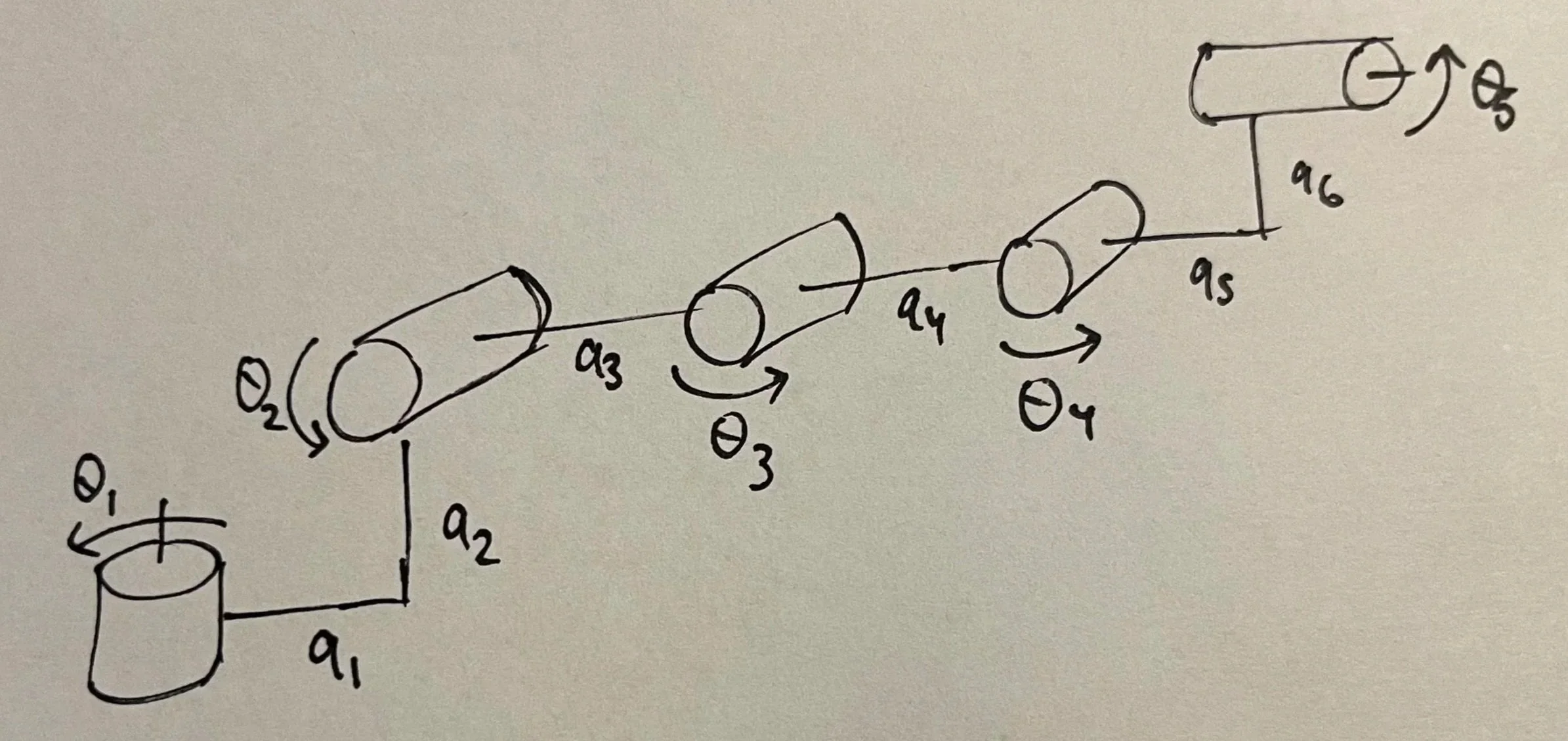
Rough diagram of the axes and motor locations

Weights and Lengths of Joints and Arms
Torque Calculations
The motors being used consist of 3 NEMA 34 motors and 2 NEMA 23 motors. Each motor will have a gearbox that outputs. The motors all have a torque curve, where more RPMs means less average torque. I estimated that I would like the motors to run in the 100-200 RPM range, so I looked up the datasheets on StepperOnline and proceeded with the calculations with the 200RPM torque values. Then I used the gear ratios of the gearboxes to calculate the theoretical best torque possible. From there, I took an estimate that I would achieve 60% efficiency because there would inevitably be friction and heat losses from being a DIY build.
I would calculate the masses of each arm and joint using the mass properties function in SolidWorks. Stainless steel parts make the build deceptively heavy! The motors are also incredibly heavy; the Nema 34s are around 3.5 to 4.5 kgs each! I tried to carve out as much weight in the later stages of the design, but it is still really heavy for my liking.

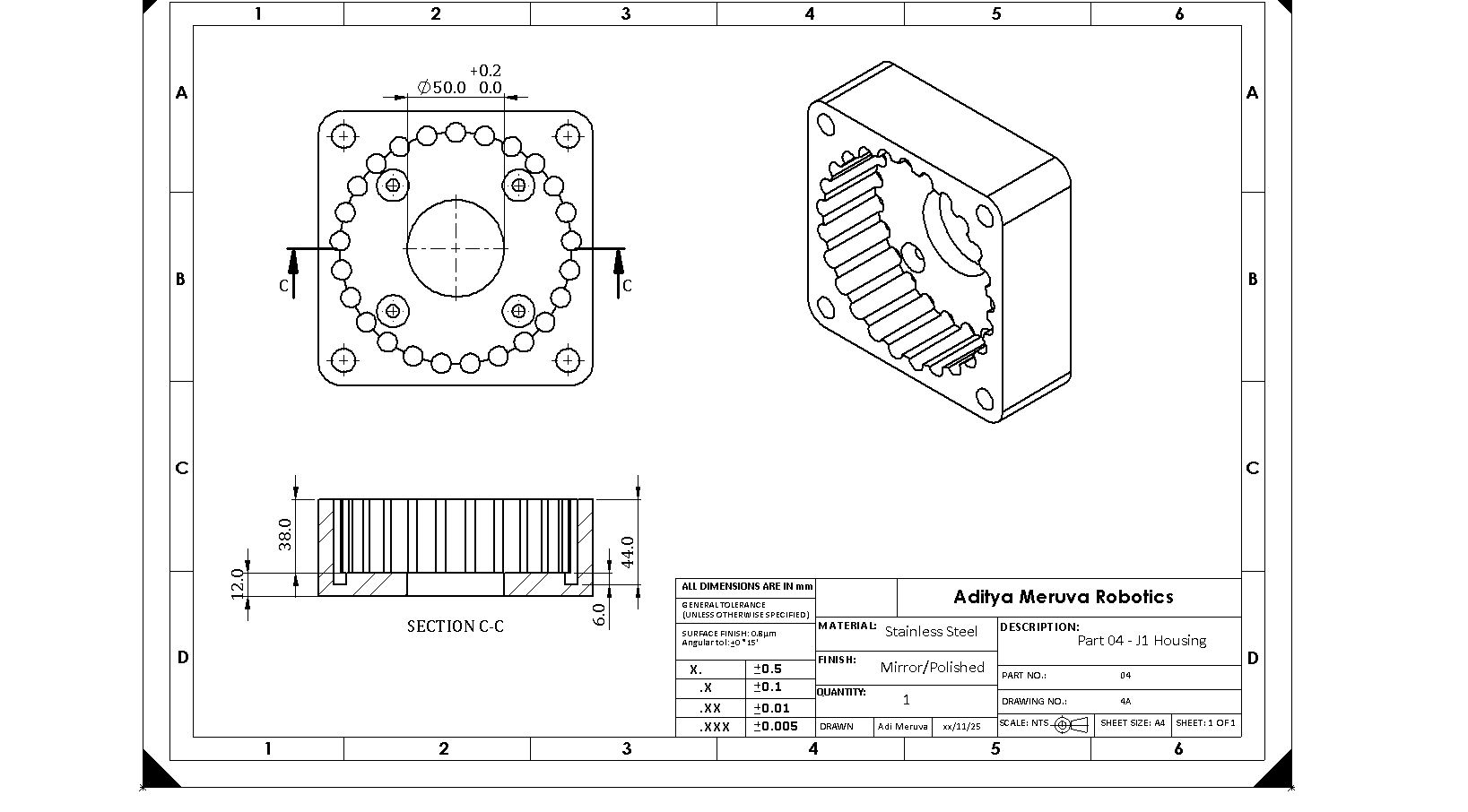
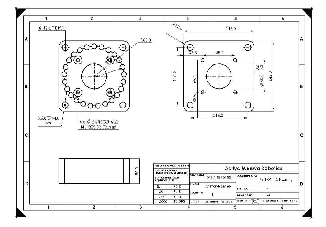
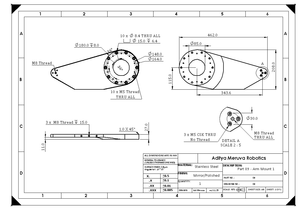
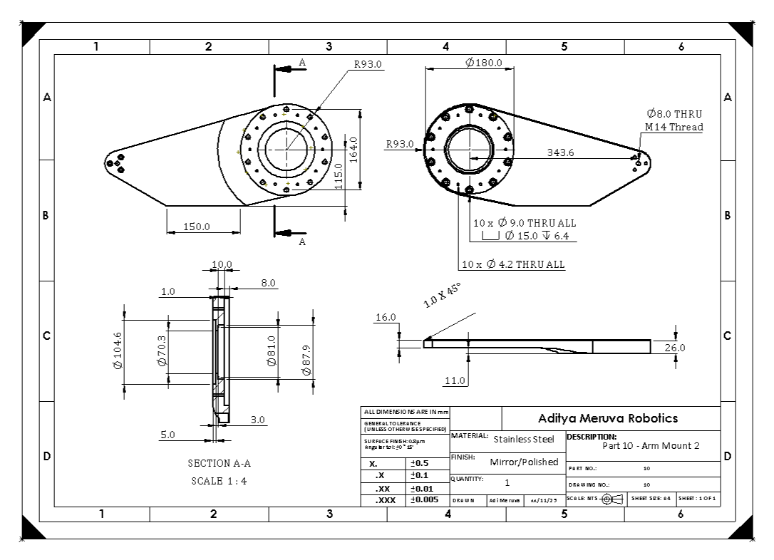
Sectional drawing view of main arm. This is just 1 page out of 4 for this specific part!
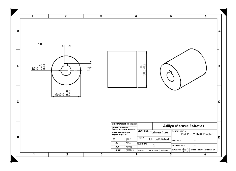
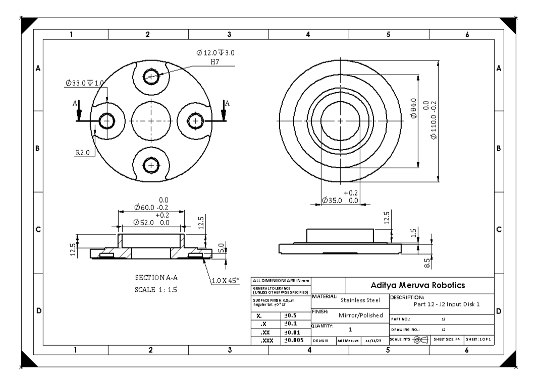
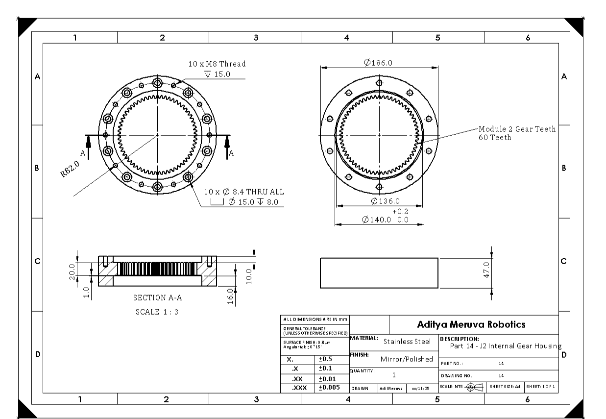
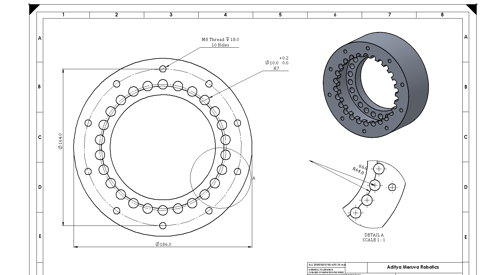
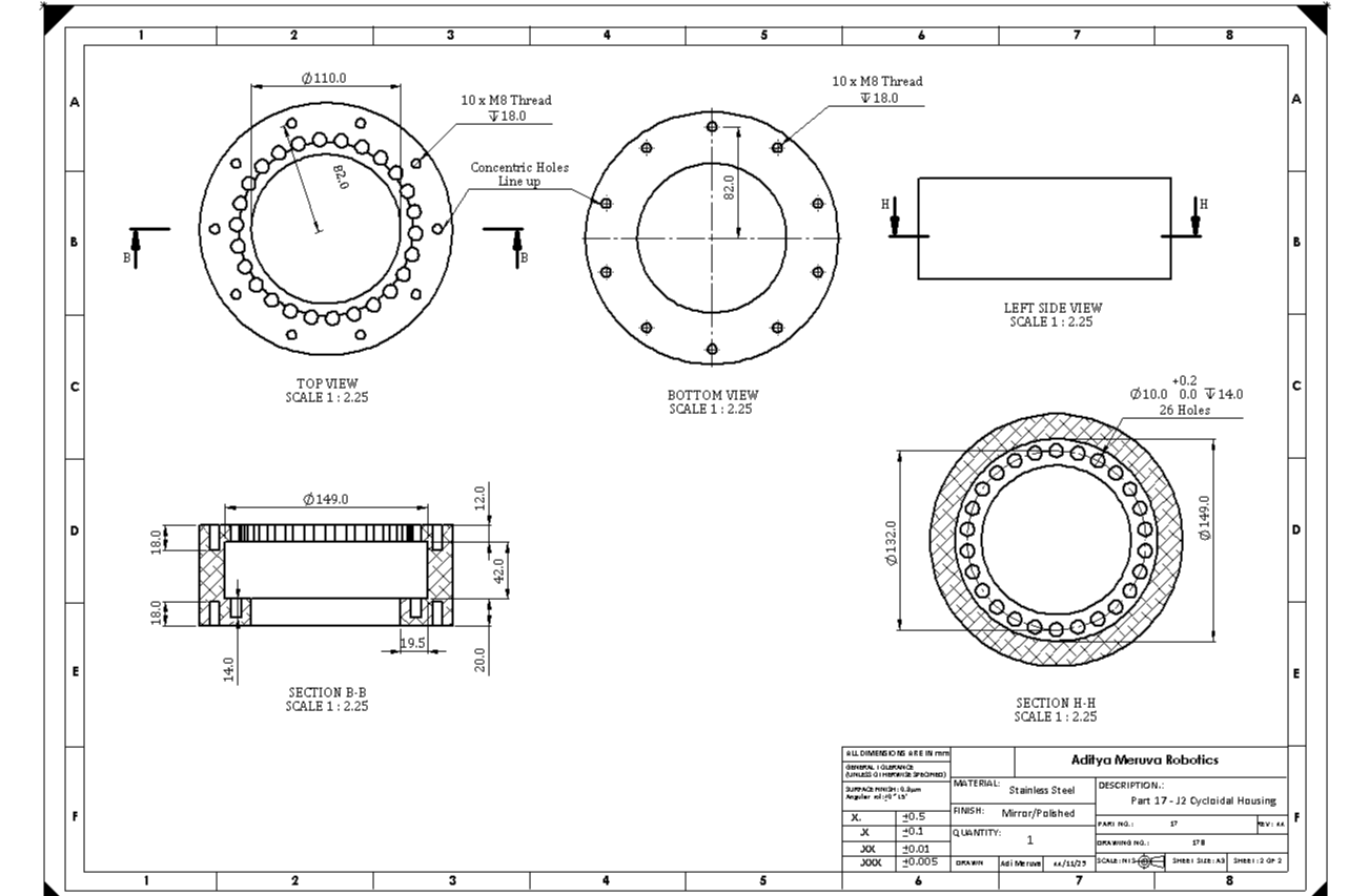
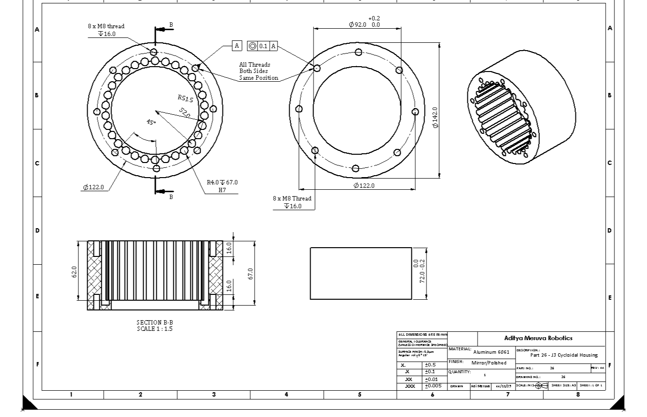
Drawings
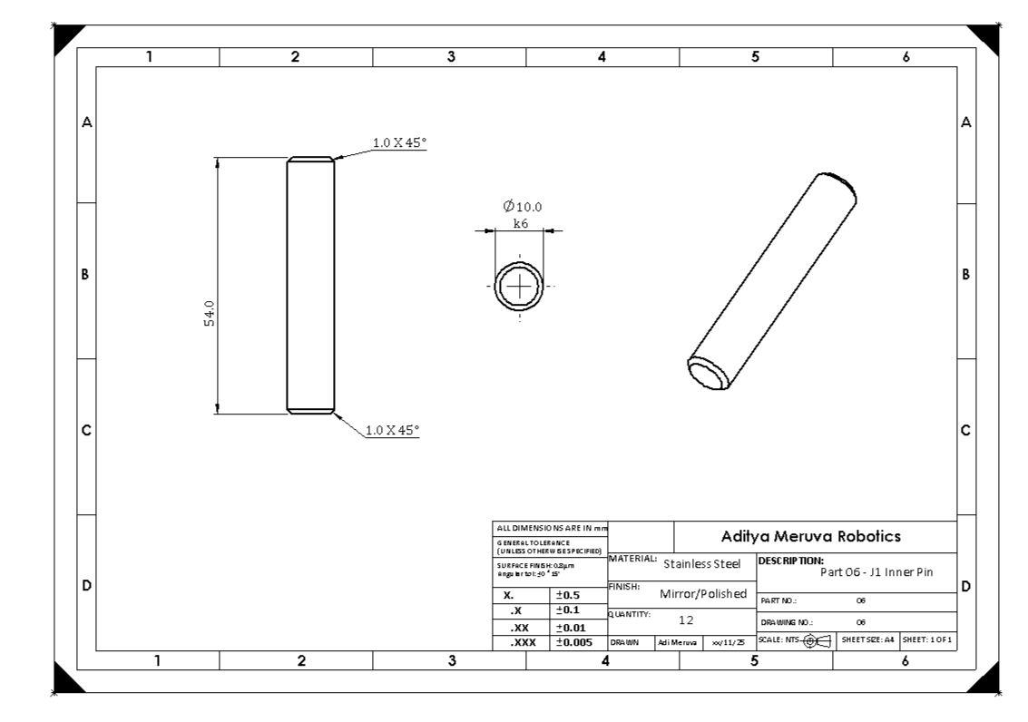
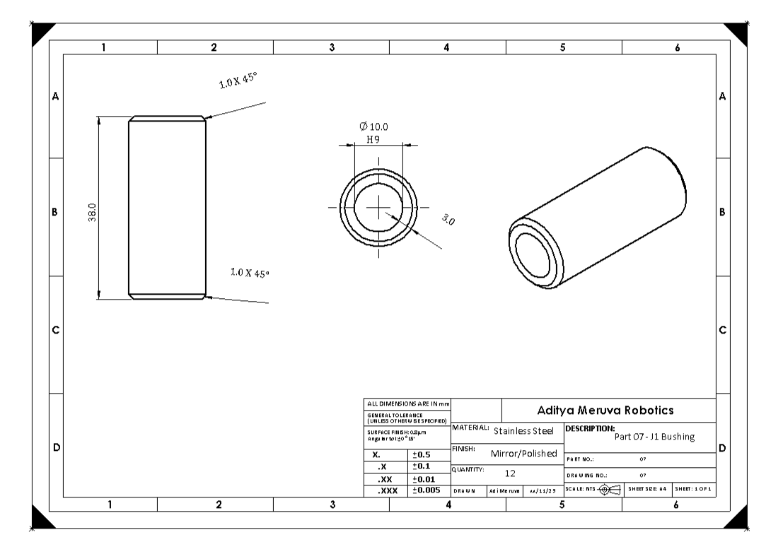
I had to make over 60 pages of drawings for this project! I had to talk with the machinists about machineability and tolerances of all the parts, and I had to make multiple revisions to adhere to DFM principles.
The machine shop usually machined to a tolerance of 0.1mm, and so many of my dimensions use the bilateral tolerance of 0.1mm. For pins and pushings, I used transition fits and clearance fits to make assembling the parts easier in the future. I utilized H7 and k6 or e6 tolerances for the pins and holes, depending on the purpose of the part. I used a little bit of GD&T with datums and callouts, such as angularity and concentricity, but it made the parts more expensive, so I did not use them much.


Components purchased so far
I have actually already purchased a lot of the heavy-duty components for the project. I have purchased the NEMA stepper motors, and also cross roller bearings! These bearings are extremely important to allow for the arms to be constrained axially while rotating. Here are some of the pictures of them, they are really quite big and heavy!
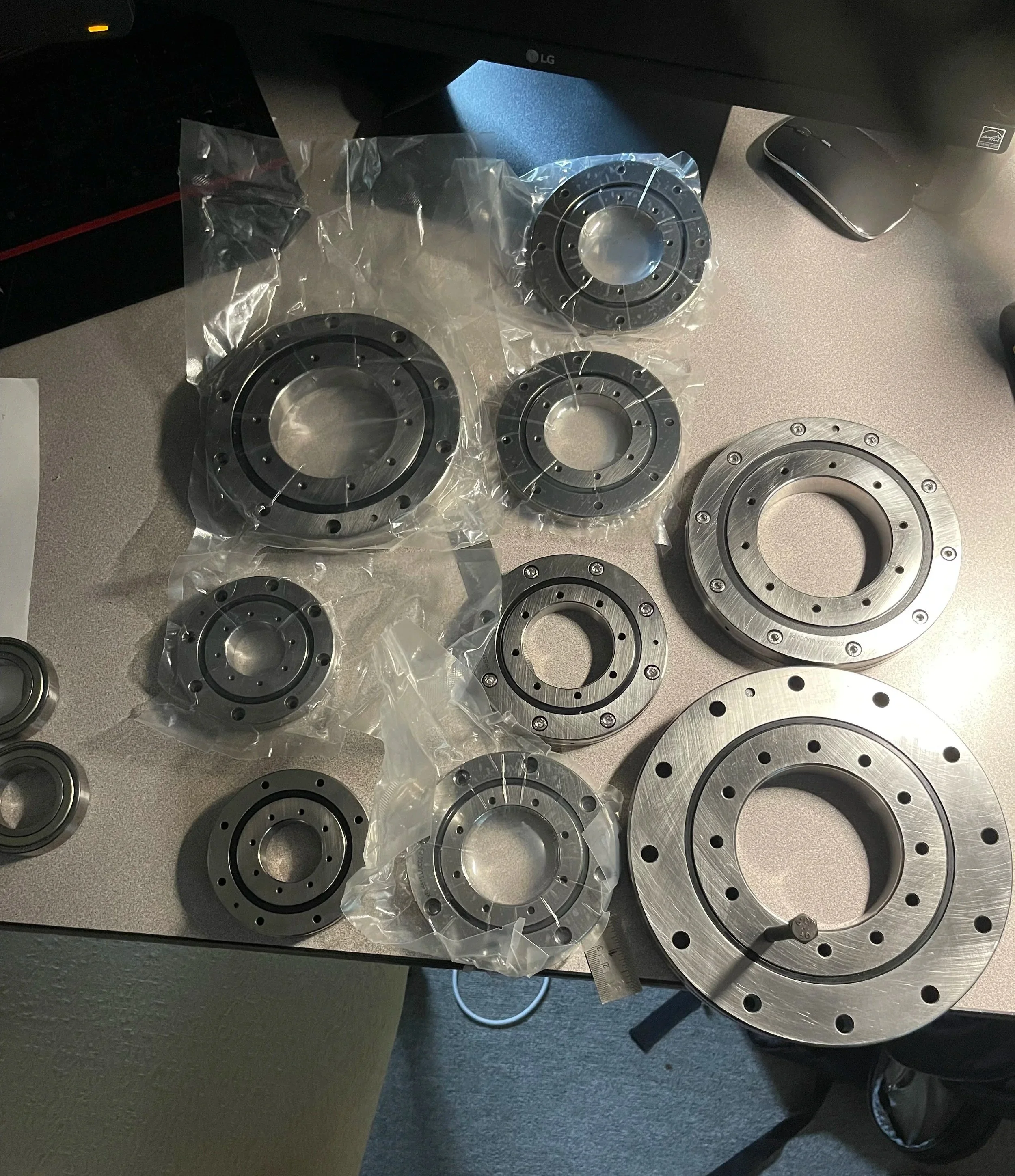
All the cross roller bearings arrived!
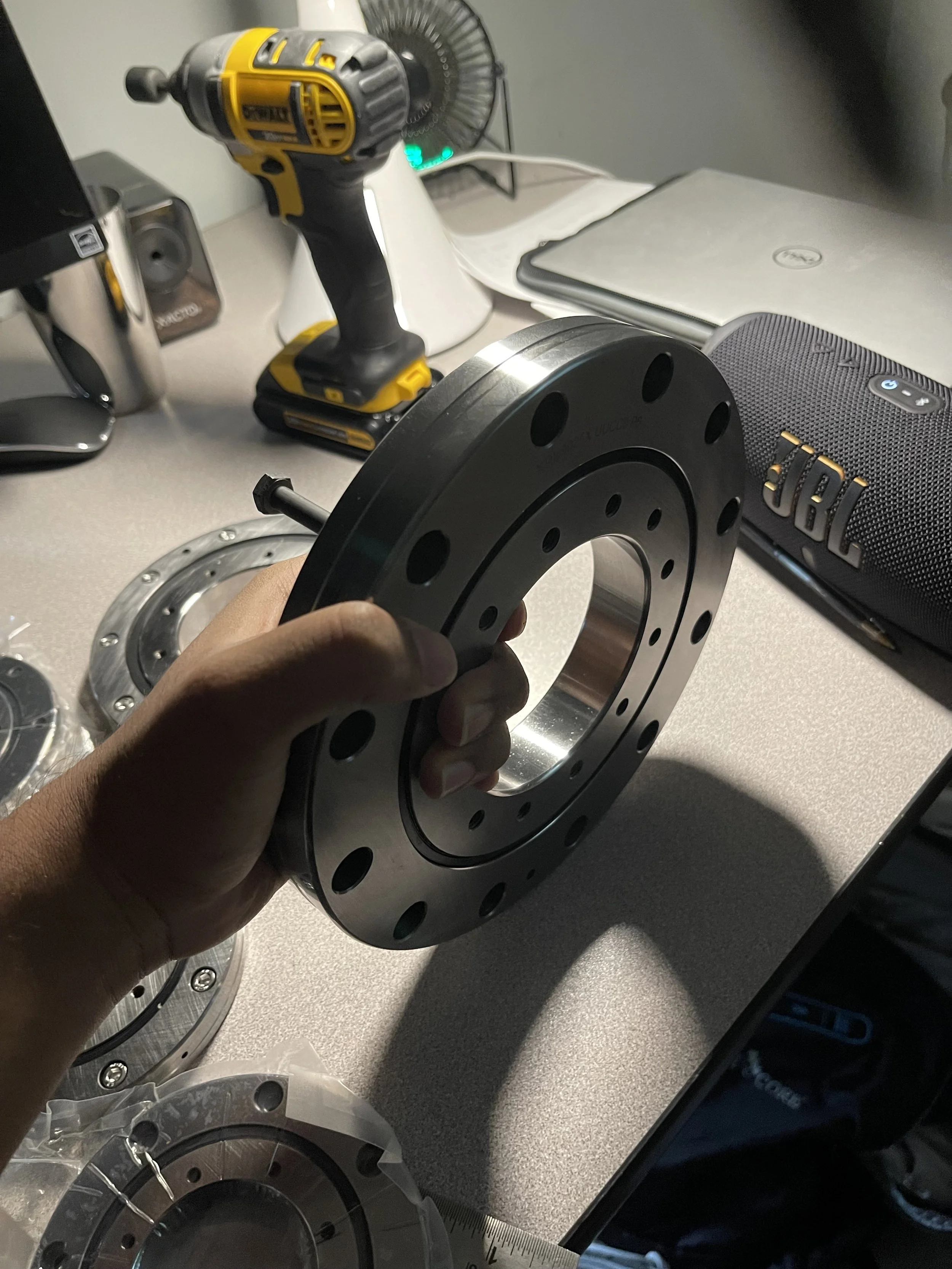
How big this roller bearing is compared to my hand!

This behemoth of a NEMA 34 Stepper Motor
Final Words
Machining is set to be complete in May 2026. I will be sure to keep the page updated, and I will work hard to complete this build! I am so happy I am reaching the final steps (or rather the middle steps) of this passion project of mine. Thanks for reading!