CAD Experience
Here is a collection of my favorite CAD portions of the projects I have done!
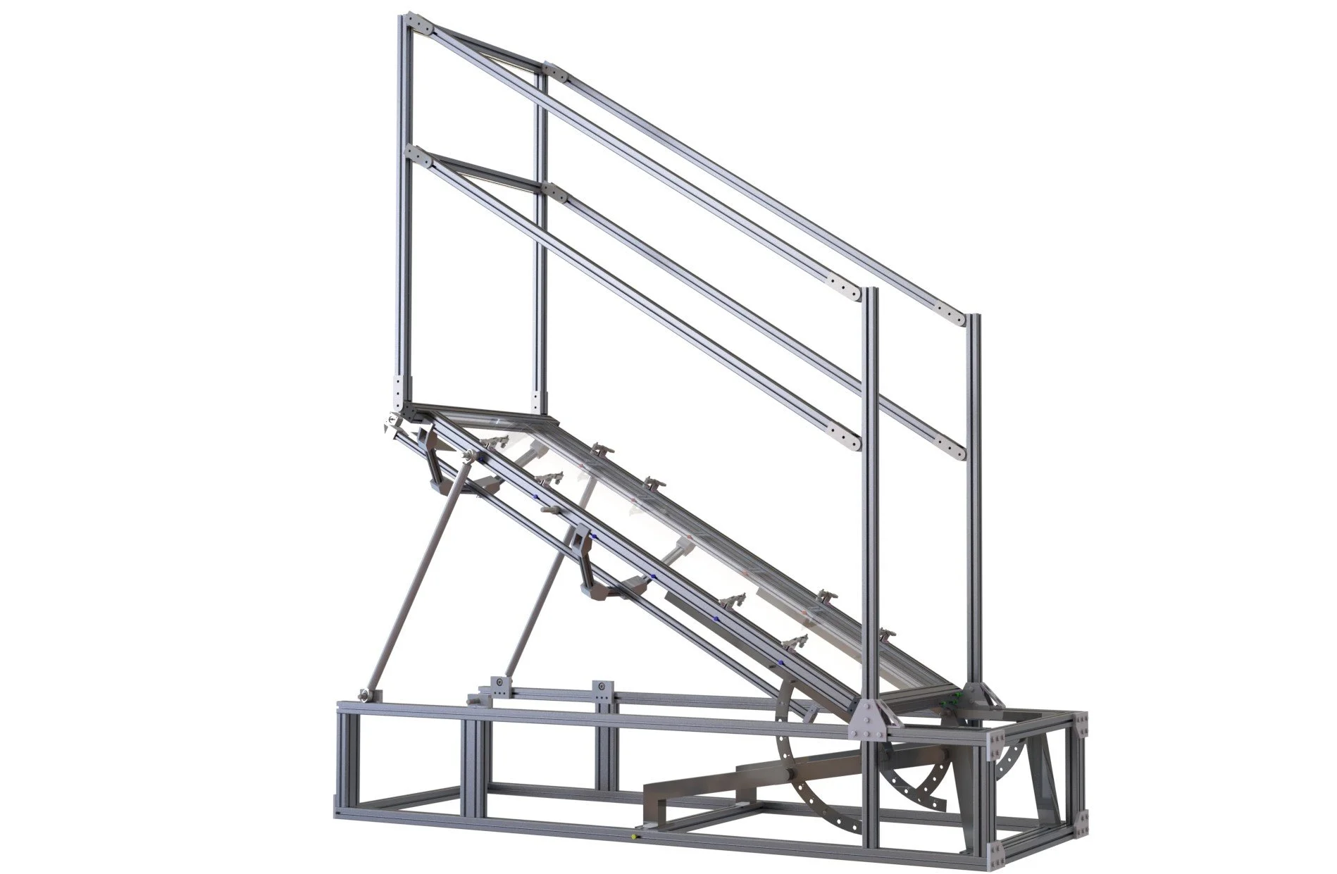
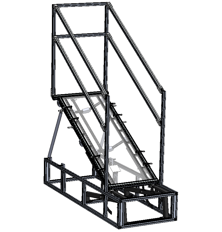
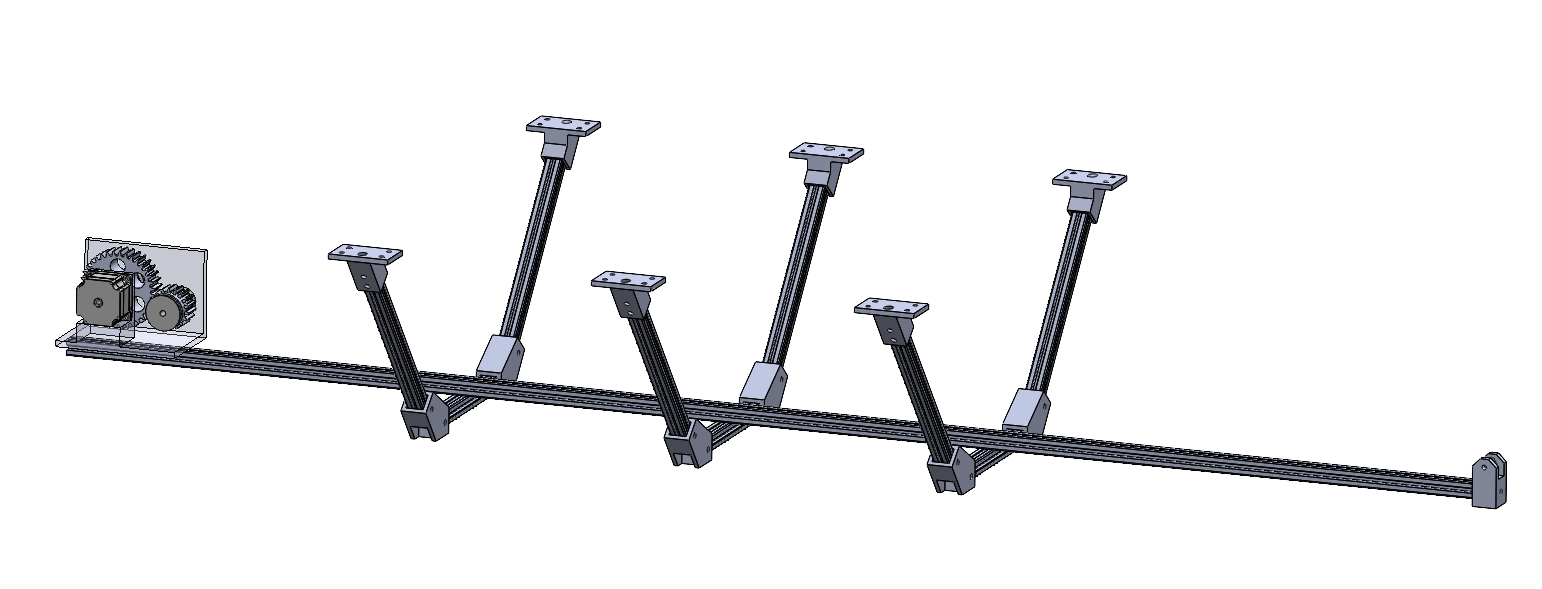
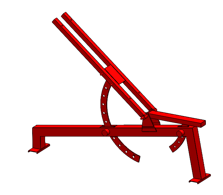
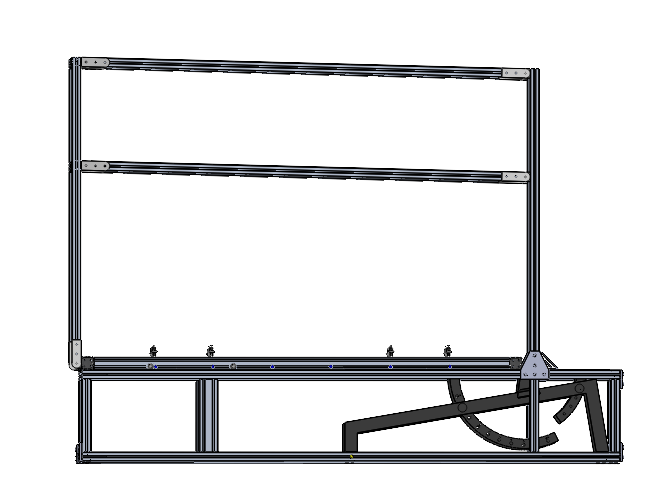
Senior Capstone - Vibram Transparent Inclinable Walkway
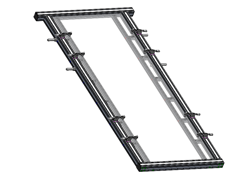
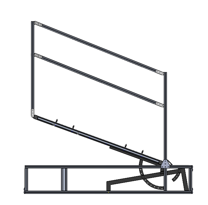
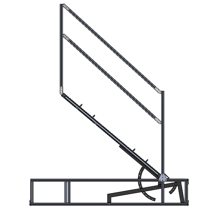
This is one of the largest assemblies I have ever made in SolidWorks, and it taught me how to optimize performance and keep things organized for modeling. I also had to learn how to present it nicely to clients and back up the design decisions in meetings. I tried to do my best with small details too, such as color-coding all the screws so it is easier for us to assemble. I also had to model the gym bench by taking measurements with a caliper and recreating it in CAD. The process for creating the CAD was for our team to have weekly meetings where we project the most up-to-date CAD on the wall, and then everyone would offer critiques and ideas on what can be improved. I would then implement these changes in SolidWorks and present the model in the next meeting.

Sensacore Autosampler
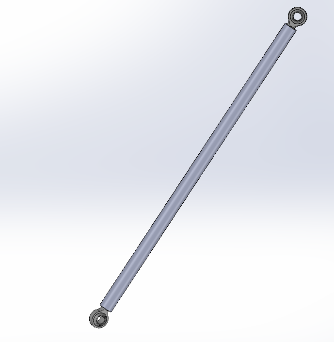
For 2 months, I was editing and improving the CAD for the device. This meant changing every single sheet metal part and also creating new ones that would increase the device's width by 40mm in total. Furthermore, I modified the lid to feature larger radii and thicker acrylic panels (5mm to 8mm) for a sleeker appearance. I redesigned the hinge assembly and back support piece of the device, so now it is a big sheet metal support that is welded to the base frame. Lastly, I added functional gas struts that I found from a vendor, and configured the gas strut in the CAD after discussing with their representative about the specifications needed.
5 Axis Robot Arm!
Overall Design
Over the course of 4 months, I meticulously designed all the components for my robot arm, putting an emphasis on machineability and ease of assembly. The complete CAD assembly has 450 components and is comprised of over 55 uniquely machined parts! The robot's total reach is projected to be 1.10 meters, and the estimated payload will be 8kg. There are 5 axes of freedom that all have custom-made gearboxes I designed. There are 4 cycloidal gearboxes for joints 1 through 4, and 1 planetary gearbox for J5. The first 3 joints near the bottom are powered by Nema 34 Stepper Motors that have 9Nm and 12Nm of holding Torque. Joints 4 and 5 are powered by Nema 23 Stepper motors that have 3 N · m of holding torque each.
360 view of the robot arm CAD, with gearboxes made transparent
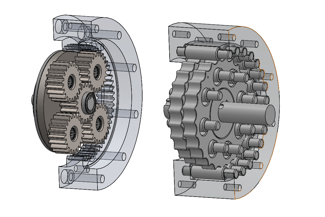
Section view of joint 2 gearbox
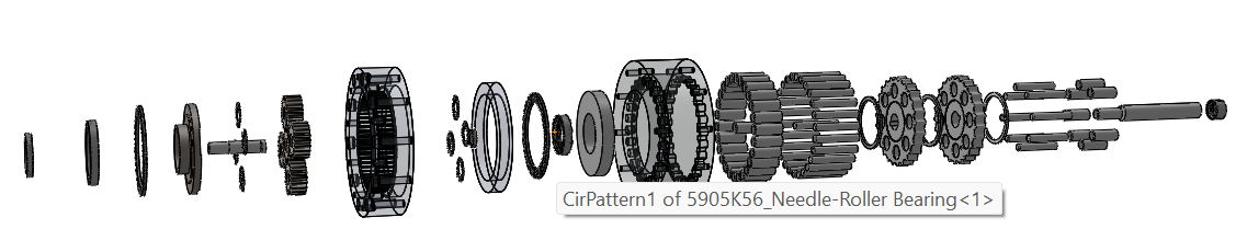
Exploded view of Joint 2 Gearbox
Gearbox Designing
The gearboxes in Joint 1-4 are cycloidal gearboxes with a 25:1 ratio, with Joint 2 also having a planetary stage that makes the ratio into 100:1. Pitcured above and to the side is the CAD model of Joint 2 in both a section view (with some parts hidden) and an exploded view.
Each cycloidal disk is created using parametric equations, and they utilize eccentric bearings that create a unique oscillation motion. Joint 5 uses a planetary gearbox to conserve weight, since cycloidal gearboxes usually have more mass in the same package than planetary. There will be backlash in the cycloidal and planetary portions of the build, and I hope to do backlash compensation in the code. The housings for the planetary gears in Joint 2 and Joint 5 are going to be made from wire EDM, while the cycloidal housings will use CNC milling. I had to make some design modifications to make sure the products were machineable, such as making the pin holes less tall because the tool heads could not reach those depths.
Peristaltic Pump Project
360 View of Peristaltic Pump
I recreated a simple peristaltic pump design that is commonplace in professional products. Usually, a strong stepper motor is attached to a frame and revolves ball bearings in a circle to squish a tube in a circular motion. The revolutions of the ball bearings push the air inside the tube and create a vacuum force in its wake. This allows for a pump that does not need priming and is extremely precise in the amount of liquid dispensed.
Exploded view of Peristaltic Pump Design
Automated Assembly Line - Bagmate
In my group, I designed 2 parts for machining in a CNC mill that feature a T-slot mechanism. This approach allowed the top and bottom parts to slide together securely, eliminating the need for the snap-fit that was difficult to machine. I had to ensure these parts would adhere to DFM principles. Once I was given the CAD models of the CNC vices, I made assemblies and then eventually CAM programs for machining the parts in the future. There are many chamfers placed on the design because a robot will be pushing the parts together, and so misalignment will be corrected by the angled openings.
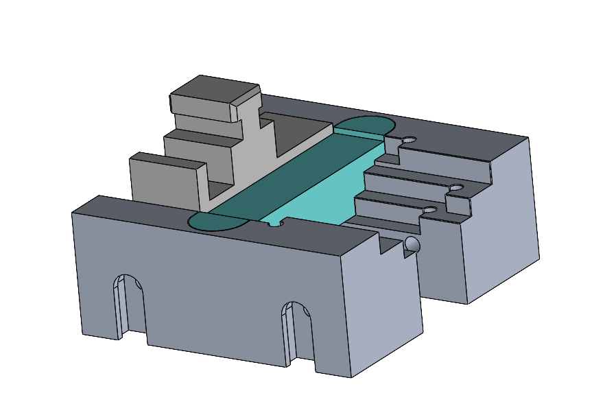
CAD part inside vice model